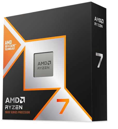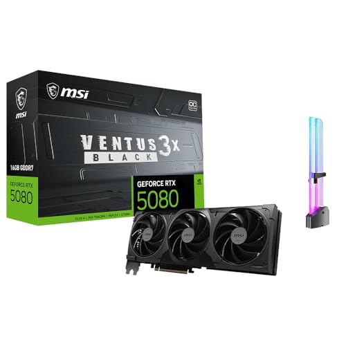

Quick Answer
Count motherboard mounting holes. Match chassis standoff layout to board holes. Install standoffs only at matching locations. Remove extra standoffs immediately. Extra standoff touching back of motherboard causes electrical short, destroying board. Place motherboard over standoffs. Visually verify every standoff centers perfectly through matching hole before driving screws.

Pros
- 24 cores and 48 threads for multi-threaded workloads
- Manufacturer-listed 5.3 GHz max boost and 152MB cache
- Quad-channel DDR5 RDIMM support listed up to 1TB
- 80 usable PCIe lanes listed for storage and expansion
- Unlocked, with automatic overclocking feature
Cons
- 350W TDP requires substantial cooling capacity
- CPU cooler not included; must be purchased separately

Pros
- 27-inch FHD anti-glare display, per listing
- Full HD camera with dual speakers
- ENERGY STAR certified, per listing
- 20Gbps USB-C ports listed in title
- Wi-Fi 6 connectivity listed
Cons
- Listing names the CPU as Ryzen AI 5 in title but Ryzen 5 in features

Pros
- 16 cores and 16 threads, up to 5.4 GHz, per listing
- 32GB DDR5 and 1TB PCIe 4.0 SSD listed
- Two USB4, HDMI 2.1, and DisplayPort 1.4 outputs
- 2.5GbE LAN with Wi-Fi 7 and Bluetooth 5.4
- OCuLink adapter listed as included
Cons
- OCuLink is non-hot-swappable and uses an M.2 slot
- Performance figures are manufacturer-stated, not independently tested
Motherboard standoff alignment is a mechanical tolerance problem with electrical consequences. A standoff that sits under an unplated area of the printed circuit board (PCB), or a hole with no standoff beneath it, creates flexure, uneven connector insertion force, or a direct short path to the chassis. This guide sets out a diagnostic procedure for verifying alignment in a new build before power is ever applied.
What Standoffs Do
Standoffs serve three engineering functions: mechanical support, electrical isolation, and controlled grounding. Mechanically, they hold the PCB at a fixed offset from the chassis tray, typically about 6 to 6.5 mm. This keeps solder joints, through-hole pin tails, and rear-side components clear of the metal. Electrically, they prevent the underside of the board from contacting the tray. Where the board is designed to ground through its mounting holes, they also provide a low-impedance return path from the board’s ground plane to the chassis.
Most ATX-class cases use brass or plated steel standoffs with a 6-32 UNC external thread and an internal thread that accepts the board screw. Hex drive sizes are typically 5 mm to 5.5 mm. Some compact or proprietary chassis use M3 threads instead, so thread pitch must be matched. Cross-threading a 6-32 screw into an M3 standoff, or the reverse, strips the brass at relatively low torque.
Manufacturer documentation specifies that the plated annular ring around each mounting hole, usually 6 to 8 mm in diameter, is the intended ground contact area. A standoff positioned outside this ring does not provide the intended contact. If it lands near traces, it can also become a short-circuit hazard.
Counting and Matching Holes
Standoff count is determined by the board, not by the case. The rule is one standoff per plated mounting hole on the board, and no standoff at any chassis position that lacks a corresponding hole. Reference form factor dimensions are:
- ATX: 305 × 244 mm, typically 9 mounting holes.
- Micro-ATX: 244 × 244 mm, typically 4 to 9 holes depending on layout.
- Mini-ITX: 170 × 170 mm, 4 holes.
- E-ATX: approximately 305 × 330 mm, often 9 to 10 holes, with the extra holes along the extended edge. Hole count and positions vary by vendor, so check the board’s manual.
To match holes, lay the bare motherboard flat on a non-conductive surface, such as the anti-static bag exterior or its retail box, and mark or note each plated hole. Compare this pattern against the chassis tray, which commonly has more embossed or perforated positions than any single board uses. Chassis trays often label positions by form factor (A for ATX, M for micro-ATX, I for ITX), but
For related maintenance and equipment benchmarks, review our technical guides on best gaming pcs, examine multitasking gaming desktops, and compare streaming pc builds. You can also reference our analyses on vr desktop performance and high-performance gaming pcs. For industry engineering standards, consult IEEE Computer Society benchmarks.