
Quick Answer
Select compatible hardware. Ground continuously in clean workspace. Mount CPU, thermal cooler, and RAM onto motherboard. Fasten motherboard into chassis. Install power supply unit and storage. Seat graphics card into primary PCIe slot. Route and attach all power cables. Boot machine, verify firmware detection, then install target operating system.

Pros
- E-ATX board for Intel Core Ultra Series 2 on LGA 1851
- Listed M.2 layout includes onboard and expander slots
- DDR5 listed up to 9200+ MT/s OC on four DIMM slots
- 3.99-inch LCD for hardware monitoring, per listing
- Thunderbolt 5 accessory card listed for rear ports
Cons
- Thunderbolt 5 relies on an accessory card, per listing
- E-ATX size and 6.8-pound weight may limit case options

Pros
- 32GB DDR4 RAM and 1TB PCIe M.2 NVMe SSD (listed)
- Intel Core i5-12400F, 6 cores and 12 threads
- Wired keyboard and mouse combo included
- Windows 11 Home pre-installed, per listing
- RJ-45 Gigabit Ethernet and dual-monitor ports listed
Cons
- Entry-level GT 1030 graphics limit demanding workloads
- Listing shows no customer reviews yet

Pros
- Four PCIe 5.0 x16 slots listed for multi-GPU use
- Four PCIe 5.0 x4 M.2 slots, per listing
- Dual USB4 Type-C ports and dual 10GbE LAN
- Wi-Fi 7 with directional antenna, per listing
- Up to 2TB ECC R-DIMM capacity, per listing
Cons
- Uses ECC R-DIMM memory, which narrows memory choices
- AI and multi-GPU performance claims are not independently verified
Planning Parts and Compatibility
Mismatch parts waste budget. Engineering evaluations indicate physical space, socket interconnects, electrical load profiles require hard math before purchase. Check specifications systematically:
- Socket and Chipset: Match CPU socket exactly (AMD AM5 / Intel LGA 1700/LGA 1851). Verify motherboard VRM (Voltage Regulator Module) matches processor TDP (Thermal Design Power) and package power tracking (PPT) limits. 14+2+1 power stages with 80A MOSFET minimum for unlocked workloads.
- Memory Topologies: Modern consumer motherboards utilize daisy-chain memory trace layout. Use two matched DDR5 modules in slots A2 and B2 for signal reflection dampening. Check memory Qualified Vendor List (QVL) against targeted data rate (6000 MT/s at CL30 for AM5 1:1 UCLK:MCLK; 6400 to 7200 MT/s for Intel gear 2). Verify operating voltages match JEDEC or XMP/EXPO profiles (1.35V to 1.45V VDD/VDDQ).
- Power Delivery (ATX 3.0 / PCIe 5.0): Compute total system consumption at continuous full-load saturation. Modern GPUs manifest high microsecond transient power excursions (spikes reaching 200% rated TDP). Utilize native PCIe CEM 5.1 / 12V-2×6 power supplies. Isolate rails or verify single +12V rail delivers total platform amperage with voltage tolerance within ±5%.
- Clearances and Enclosure Volumes: Verify GPU dimension clearance (length, width, slot thickness). Cross-reference top-mounted AIO (All-In-One) radiator clearance against motherboard VRM heatsink height and RAM heat-spreader height (standard clearance: 40 mm).
Safety and Tools
Static charges fry silicon gates without tactile sensation. Human ESD threshold is 2,000V; gate oxide breakdown occurs at sub-100V.
| Tool / Protection | Specification | Function |
|---|---|---|
| Screwdriver | #2 Phillips magnetic tip, 150mm shaft | Standard chassis, motherboard, PSU fasteners |
| Torque Limiter | 0.6 Nm preset, 1/4-inch hex drive | CPU socket retention, cooler bracket torque spec |
| Precision Driver | #1 Phillips / Torx T8 | M.2 heatsink retention screws (0.2 Nm limit) |
| Thermal Interface | Non-conductive paste (>8.5 W/m-K) | Die/IHS to cold plate thermal transfer |
| Solvents | 99% Anhydrous Isopropyl Alcohol (IPA) | De-greasing IHS surface, residue removal |
| ESD Grounding | Wrist strap with 1 MΩ resistor | Drain static charge to earth ground |
Disconnect AC mains during assembly. Never construct platform over carpet surfaces. Connect anti-static ground clamp to unpainted metal grounding surface or cold earth ground pin.
Assembly Step by Step
Perform out-of-chassis baseline assembly first on non-conductive motherboard cardboard container. Isolate variables before case integration.
1. CPU Installation
LGA sockets use fragile spring pins; do not touch socket array.
- Release retention lever by pushing down and outward from bracket clip. Swing load plate upward.
- Locate triangle pin-1 index markers on CPU substrate and motherboard socket frame.
- Hold CPU solely by substrate edges. Lower CPU vertically into socket housing without lateral tilt or slide. Verify seating into alignment keys.
- Lower load plate. Swing retention lever into locked position under retention catch. Retain socket plastic cover; component ejects automatically under tension.
2. M.2 Solid-State Drive Installation
Primary storage lanes route directly to CPU PCIe root complex. Mount drive to primary slot (Slot 1, nearest CPU socket).
- Remove integrated motherboard heatsink assembly with #1 Phillips driver.
- Inspect M.2 slot for pre-installed standoff at 2280 form factor point (80 mm length). Relocate standoff if configured for alternate length.
- Insert M.2 NVMe SSD into M-key connector at 30-degree incline until fully seated.
- Compress SSD horizontal onto standoff. Fasten retention latch or screw to 0.2 Nm torque to avoid PCB warping.
- Remove blue protective polymer film from thermal pad underneath integrated motherboard heatsink. Mount heatsink and tighten retaining screws in alternating diagonal sequence.
3. DRAM Seating
- Open retention clips on memory slots A2 and B2 (Channel A Slot 2, Channel B Slot 2).
- Align notch on DDR5/DDR4 module bottom interface edge with plastic key in motherboard DIMM slot. Memory notches are asymmetrical.
- Apply direct, balanced vertical pressure on both module upper corners simultaneously until retention latches swing inward and lock with audible mechanical click.
4. Chassis Preparation and Motherboard Integration
Motherboard standoffs prevent dead shorts between traces and chassis tray.
- Verify standoff positions inside case match motherboard form factor (ATX layout requires 9 points). Remove unused brass standoffs to prevent short-circuiting backplane components.
- Install I/O backplate shield if not integrated directly to motherboard rear cluster.
- Maneuver motherboard into chassis at slight angle; align rear I/O cluster into backplate cutout. Drop motherboard onto center alignment dowel pin.
- Drive motherboard screws using #2 Phillips driver into standoffs in cross-pattern. Fasten to 0.5-0.6 Nm torque. Do not over-torque; high clamping stress crushes circuit trace layers around screw lands.
5. Power Supply and Cable Routing
Pre-route power delivery lines prior to cooler and expansion card installation to preserve hand clearance.
- Orient PSU fan facing outward toward chassis dust filter vent. Secure PSU housing to chassis rear with four coarse-thread hex screws.
- Route and insert 24-pin ATX main motherboard power connector until latch engages fully.
- Route dual 8-pin EPS12V CPU power leads through top chassis cutouts. Seat connectors into top-left motherboard sockets.
- Route dedicated PCIe power or native 12V-2×6/12VHPWR harness through lower shroud grommets.
Critical Safety Warning: Ensure 12V-2×6 / 12VHPWR connectors are seated completely flush against the terminal housing with zero gap visible between the connector body and receptacle. Terminal pins carrying up to 9.2A per circuit will overheat and melt if partial engagement causes resistance spikes. Maintain straight cable orientation for a minimum of 30 mm before initiating bends.
6. CPU Thermal Interface and Cooling Solution
- Clean CPU Integrated Heat Spreader (IHS) and cooler cold plate with 99% isopropyl alcohol and lint-free wipe. Allow complete solvent evaporation.
- Affix cooler retention bracket to motherboard through backplate assemblies.
- Apply thermal paste: Central pea-sized deposit (approx. 5-6 mm diameter) or cross pattern for oversized spreaders (Intel LGA 1700). Engineering evaluations indicate proper mounting pressure forces uniform paste distribution across micro-crevices.
- Seat cooler base plate directly down onto processor. Alternate tightening retention thumb-screws or spring-loaded nuts by two full turns per corner in an X-pattern. Continue until mechanical stops engage or 0.6 Nm torque limit is achieved.
- Connect cooling fan PWM signal connector to
CPU_FANheader. Connect liquid cooler pump tachometer lead toAIO_PUMPorW_PUMP+header.
7. Front Panel and Ancillary I/O Connections
Consult motherboard schematic mapping for front panel block pins (usually bottom-right edge):
POWER_SW: Momentary toggle switch. Non-polarized.RESET_SW: Momentary toggle switch. Non-polarized.HDD_LED/PWR_LED: Polarized diodes. Positive lead (pin 1) marked with (+) or indicated by solid trace wire.USB 3.2 Gen 1: 19-pin header. Fragile pins; align keyed shroud notch to cable keyway before inserting.HD_AUDIO: Keyed via missing pin position 8. Connect to lower audio codec edge.
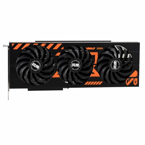
8. Graphics Card (GPU) Installation
- Remove chassis expansion slot metal blanking brackets corresponding to primary PCIe x16 slot position (typically slots 2 and 3).
- Release mechanical PCIe slot retention latch at rear of motherboard PCIe x16 connector.
- Align GPU PCIe expansion edge connector over primary x16 slot. Apply vertical pressure until latch snaps upward into locked position.
- Secure metal bracket to case chassis chassis frame using standard 6-32 machine screws.
- Connect 12V-2×6 or discrete 8-pin PCIe cables. Never daisy-chain single multi-drop pigtail cable on loads exceeding 225W; feed each 8-pin input with independent power supply harness.
First Boot and OS Setup
Connect display directly to GPU output interface (DisplayPort/HDMI), not motherboard I/O, unless using integrated graphics for troubleshooting. Connect keyboard and power cable.
POST Verification
Depress chassis power switch. Observe motherboard debug segment display or 4-stage Diagnostic Q-LED sequence (CPU -> DRAM -> VGA -> BOOT). DDR5 platforms execute memory training on first cycle; display output may remain dark up to 180 seconds while controller maps signal timing. System displays American Megatrends or vendor POST splash screen upon success.
BIOS/UEFI Configuration
- Strike
DELorF2key continuously during initialization to enter UEFI setup. - Confirm firmware identifies CPU model, correct core counts, and all installed RAM banks at stock JEDEC speeds.
- Confirm storage subsystem identifies connected NVMe SSD.
- Update UEFI firmware via built-in flashing utility (e.g., EZ Flash, Q-Flash) using clean FAT32 USB drive containing latest stable microcode payload.
- Enable AMD EXPO or Intel XMP profile to shift memory clocks from baseline (4800 MT/s) to rated module spec (e.g., 6000 MT/s) with optimal primary/secondary sub-timings.
- Configure fan curve logic: Set fan headers to PWM (Pulse-Width Modulation) mode rather than DC voltage control. Set fan ramp hysteresis to 2-3 seconds to avoid thermal cycling fan rpm thrashing on momentary CPU core boost states.
- Save configurations and restart (Press
F10).
Operating System Installation and Drivers
- Insert bootable USB flash drive formatted with Windows 11 installation media (GPT partition scheme, UEFI target mode).
- Boot system, press
F8orF11for boot menu, select UEFI USB partition. - Proceed through installation sequence to disk selection screen. If target NVMe drive does not report, provide Intel VMD or AMD RAID controller driver via secondary directory path. Partition scheme must use GUID Partition Table (GPT) to support Secure Boot and modern TPM 2.0 requirements.
- Complete operating system setup without connecting to network if avoiding mandatory telemetry cloud account creation.
- Install chipset drivers downloaded directly from silicon vendor (AMD Chipset Drivers or Intel INF/Management Engine), not generic motherboard disc packages. Reboot.
- Install GPU display driver. Select clean installation configuration.
- Execute Cinebench (multi-thread) combined with FurMark/3DMark stress tests for 30 minutes. Monitor metrics using HWiNFO64: CPU core temperatures should stabilize below 95°C (thermal throttling limit), GPU core below 83°C, GPU hotspot below 105°C, with +12V rail maintaining minimum 11.40V under combined peak load.
For related maintenance and equipment benchmarks, review our technical guides on best gaming pcs, examine multitasking gaming desktops, and compare streaming pc builds. You can also reference our analyses on vr desktop performance and high-performance gaming pcs. For industry engineering standards, consult IEEE Computer Society benchmarks.
Frequently Asked Questions
How long does it take to build a gaming PC?
Physical assembly requires 1 to 2 hours for standard configurations. Liquid-cooled topologies, complex RGB routing hubs, and custom cable management expand build times to 3 to 4 hours. Initial UEFI updates, OS installation, storage formatting, driver deployments, and thermal/stability burn-in tests add another 2 to 4 hours. Budget 4 to 6 continuous hours total for complete assembly and rigorous validation.
What tools do I need?
Mandatory tools: #2 Phillips screwdriver with magnetic shaft, #1 Phillips precision driver for M.2 drives, flush cutters for cable zip ties, and anti-static wrist strap. Highly recommended: 0.6 Nm torque-limiting screwdriver for LGA bracket and cooler mounts to avoid PCB micro-fractures, 99% isopropyl alcohol for thermal interface cleanup, and thermal compound rated >8.5 W/m-K.
What should I do if it doesn’t turn on?
Execute systematic fault-tree diagnosis:
- Verify Power Delivery: Check PSU rocker switch set to
|(ON). Confirm 24-pin ATX and 8-pin EPS cable latches fully engaged. Test PSU isolation: disconnect cables, apply paperclip jumper between pin 16 (PS_ON#, green wire) and pin 17 (Ground, black wire) to test PSU fan activation. - Bypass Front Panel Switch: Front panel switch may be defective or miswired. Short Motherboard
PWR_BTNandGNDpins directly with flat-head screwdriver blade. - Read Diagnostic LEDs: Motherboard Q-LED indicators stop at point of hardware fault.
DRAM LEDstatic: Reseat modules in slots A2/B2. Test single stick in slot A2. Clear CMOS memory by jumpingCLRTCpins for 10 seconds with power disconnected.CPU LEDstatic: Check 8-pin EPS connector. Inspect CPU socket pins for bends. Verify BIOS firmware version supports processor stepping.VGA LEDstatic: Reseat GPU into slot. Re-verify 12V-2×6/PCIe power cable full seating. Try auxiliary PCIe output or integrated CPU graphics.
- Strip to Minimum POST Configuration: Remove motherboard from chassis to eliminate standoff grounding shorts. Bench-test with CPU, single stick of RAM in slot A2, GPU (or internal graphics), and power supply. Disconnect all SATA drives, front panel USB headers, and external peripherals.