
Quick Answer
Stuck orange or yellow DRAM LED signals incomplete memory training or hardware fault. Wait several minutes for initial training to complete. If unresolved, clear CMOS to reset BIOS timings. Reseat RAM modules firmly. Test single stick in primary motherboard slot, alternating modules to isolate defective memory or damaged socket.
Pros
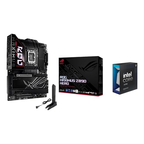
- LGA 1851 socket for Intel Core Ultra series 2 processors
- Four DIMM slots, up to 192GB DDR5, listed up to 9200+ MT/s OC
- Up to six M.2 slots and four SATA ports per listing
- WiFi 7 with Thunderbolt 5, HDMI and DisplayPort listed
- Robust power stages with ProCool II connectors per listing
Cons
- Title includes a processor; bundle contents are not confirmed
- Specification fields are minimal, with size shown as a model name

Pros
- Fast 6400MHz rated speed with low CL32 latency
- 64GB capacity across a clean two-stick setup
- Patented DHX cooling with forged aluminum heatspreaders
- 11 individually addressable RGB LEDs per module
- Swappable top bar allows physical customization
Cons
- Tall 2.26-inch height may interfere with bulky CPU air coolers
- Specifically configured for Intel XMP without listed AMD EXPO support

Pros
- 48GB single module, DDR5-5600 per manufacturer
- ECC UDIMM with 2Rx8 rank listed
- Lists many ASUS X870E and B850 boards
- Manufacturer-stated lifetime replacement warranty
Cons
- Compatibility depends on board model and slot rules
- Compatibility and specs are manufacturer-stated claims
What the LED Means
The DRAM status LED on a desktop motherboard is part of the Q-LED, EZ Debug LED, or equivalent diagnostic cluster. Manufacturer documentation from ASUS, MSI, Gigabyte, and ASRock specifies that the indicator illuminates while the platform firmware is executing the memory initialization stage of the power-on self-test (POST). On AMD AM4 and AM5 systems this stage is handled by AGESA. On Intel LGA1700 and LGA1851 platforms it is handled by the Memory Reference Code (MRC) in the UEFI image. The LED remains lit until the firmware reports that DRAM is trained, addressable, and passing basic read/write verification.
A steady orange or yellow DRAM LED that persists beyond the expected training window indicates that the initialization routine has stalled or failed. The color varies by vendor. Some boards use amber for “in progress” and red for “fault”, while others use a single amber or yellow LED for both conditions. Board manuals should be consulted for the exact definition. The underlying failure categories are consistent across vendors:
- Memory training failure caused by unstable timings, excessive frequency, or marginal signal integrity (for example, an aggressive XMP/EXPO profile at DDR5-6400 or higher).
- Poor electrical contact between the DIMM edge connector and the slot contacts, caused by incomplete seating, oxidation, or debris.
- Incompatible or defective modules, including unsupported densities, mixed kits, or failed DRAM ICs.
- Slot or trace faults, including bent CPU socket pins (LGA) or damaged memory channel routing, since the memory controller is integrated in the CPU.
- Outdated firmware lacking the memory-compatibility tables or AGESA/MRC microcode required for the installed kit.
- Power delivery anomalies on VDD, VDDQ, VDD2 (DDR5), or VDDIO/VDDQ (platform-dependent), including PSU instability under load transitions.
For reference, JEDEC DDR4 operates at a nominal 1.2 V, while XMP profiles typically specify 1.35 V. JEDEC DDR5 operates at a nominal 1.1 V on VDD and VDDQ, with the on-module power management IC (PMIC) generating the rails from a 5 V input. Because DDR5 modules regulate voltage on the DIMM itself, PMIC faults or marginal contact on the 5 V pins can produce a persistent DRAM LED with no other symptom.
Wait, Reseat and Clear CMOS
Step 1: Allow the training cycle to complete. Memory training is the first diagnostic action because it is the most frequent cause of an apparently stuck LED on a healthy system. After a first boot, a BIOS update, a CMOS clear, or a memory change, DDR5 platforms perform extended training that can hold the LED for an extended period with a blank display and no fan or RGB change. Technical analysis of platform behavior indicates that a wait of at least 5 minutes is warranted before concluding that the process has stalled. Boards with high-capacity kits (64 GB to 192 GB) may need up to 10 minutes on the first boot. Observe the motherboard’s debug LED or two-digit Q-Code display if present, because a changing code indicates active progress while a frozen code indicates a stall.
Step 2: Hard power cycle. If the LED persists beyond 10 minutes, shut down using the PSU rear switch (set to O), unplug the AC cord, and hold the case power button for 15 seconds to discharge residual charge in the bulk capacitors. This also drains standby rails (5VSB) that keep the firmware state latched.
Step 3: Reseat the modules. Release the retention latches on both ends of the slot and withdraw each DIMM vertically. Inspect the gold contact fingers for discoloration, scratches, or debris. If contamination is present, clean with 99% isopropyl alcohol on a lint-free swab and allow 60 seconds of drying time. Do not use abrasive erasers, which remove the gold plating (typically 0.76 µm to 1.5 µm thick) and accelerate future oxidation. Reinsert the module with even, firm pressure at both ends until the latches snap into place. Seating force for DDR4 and DDR5 is typically in the range of 8 kgf to 15 kgf (approximately 80 N to 150 N), which is why a distinct click should be heard and the latches must be fully closed.
Step 4: Clear CMOS. A CMOS clear resets the firmware to default settings, discards cached memory training data, and removes any manual or XMP/EXPO overrides that may have destabilized the memory subsystem. Two methods apply:
- Rear I/O Clear CMOS button (where fitted): with AC power disconnected, hold the button for 5 to 10 seconds.
- Jumper method: with AC disconnected, bridge the CLRTC pins with a jumper for 10 seconds, then restore the jumper to its original position.
- Battery method (fallback): remove the CR2032 cell (nominal 3.0 V) for at least 5 minutes with AC disconnected, then reinstall with correct polarity.
After clearing, boot with the memory at JEDEC default speeds (DDR4-2133/2400 or DDR5-4800) before re-enabling XMP or EXPO. If the system posts at default settings but fails with the profile enabled, the kit is operating beyond what the memory controller or board layout can sustain. Reducing frequency by one step (for example, from DDR5-6400 to DDR5-6000), relaxing primary timings, or manually setting VDDQ and SoC voltage within manufacturer limits is the appropriate remedy. On AM5, the SoC voltage should not exceed 1.30 V, a limit established by AMD following early EXPO-related failures. Also consider a firmware update using the BIOS Flashback feature, which flashes without a CPU or DRAM installed.