
Quick Answer
8-layer PCB improves signal integrity and power delivery over 6-layer PCB. Critical for PCIe 5.0 and high-speed memory. Layer count alone guarantees nothing, plus makers rarely publish specs. Base purchase decisions on VRM thermal tests, memory frequency validation, PCB trace routing, and trusted hardware reviews, not layer count.

Pros
- Supports a wide range of AMD Ryzen AM5 processors, including Ryzen 9000, 8000, and 7000 series.
- Includes modern connectivity such as Wi-Fi 6E, 2.5GbE LAN, USB-C, and PCIe 5.0.
- Four DDR5 DIMM slots make it suitable for current-generation memory builds.
- DIY-friendly hardware features can simplify GPU and SSD installation.
Cons
- Micro-ATX form factor offers less expansion room than a full-size ATX motherboard.
- Only two M.2 slots may be limiting for users planning multiple NVMe drives.
- The manufacturer specs do not list a full rear I/O breakdown, so buyers should verify port needs before purchase.
Overview: The GIGABYTE B850M Eagle WIFI6E is a micro-ATX AM5 motherboard built for AMD Ryzen 9000, 8000, and 7000 series processors. It presents itself as a compact, modern board with a practical feature set for mainstream builders.
Performance and Features: With four DDR5 DIMM slots, an 8+2+2 power design, PCIe 5.0 support, two M.2 slots, USB-C, Wi-Fi 6E, and 2.5GbE LAN, this board is aimed at fast everyday gaming and productivity systems. The EZ-Latch features and Wi-Fi EZ-Plug also make the build process easier for users who want a cleaner DIY experience.
Drawbacks: The micro-ATX layout naturally provides less expansion space than a full-size ATX motherboard. It also includes only two M.2 slots, which may be enough for many users but could feel restrictive for heavier storage builds.
Verdict: This motherboard is a strong fit for buyers who want AM5 compatibility, DDR5 support, and modern networking in a compact package. It is best suited to mainstream Ryzen builds rather than users who need the maximum number of expansion slots.

Pros
- Broad CPU compatibility across AMD Ryzen 9000, 8000, and 7000 series
- Strong connectivity options with Wi-Fi 6E, Bluetooth 5.3, USB 10Gbps Type-C, and 2.5G LAN
- Useful storage layout with one Gen5 M.2 slot and one Gen4 M.2 slot
- Cooling hardware is included for VRMs, chipset, and M.2 drives
Cons
- The main graphics slot is PCIe 4.0 x16, so it does not add PCIe 5.0 GPU support
- DDR5 8200+ MT/s is an overclocked speed, so real-world memory results will depend on the CPU and RAM kit used
- Wi-Fi 6E performance depends on having a compatible router and network environment
Overview: The MSI B850 Gaming Plus WIFI6E is an ATX motherboard built for AMD's AM5 platform and supports Ryzen 9000, 8000, and 7000 processors. It has a gaming-focused layout with integrated cooling hardware and a clean feature set aimed at modern desktop builds.
Performance and Features: This board stands out for its DDR5 support up to 8200+ MT/s overclocked, one PCIe 4.0 x16 slot with Steel Armor, and dual M.2 connectors including one Gen5 x4 slot. Network connectivity is also strong, with Wi-Fi 6E, Bluetooth 5.3, and 2.5G LAN for users who want flexible, high-speed connections.
Drawbacks and Considerations: It is important to note that the primary graphics slot is PCIe 4.0 rather than PCIe 5.0, and the highest memory speed is an overclocked rating rather than a guaranteed outcome. The ATX form factor may also be too large for smaller cases.
Verdict: Overall, this is a solid choice for AMD builders who want a well-equipped AM5 motherboard with fast storage, modern networking, and good thermal features. It is best suited to gamers and DIY users who value balance, upgrade flexibility, and practical connectivity over premium flagship extras.
Pros
- Strong AM5 platform support for the latest Ryzen desktop CPUs.
- Modern connectivity includes Wi-Fi 6E, 2.5Gb LAN, and USB Type-C options.
- Helpful installation features reduce build time and make upgrades easier.
- Good storage expansion with three onboard M.2 slots.
Cons
- Only one M.2 slot supports PCIe 5.0, while the other two are limited to PCIe 4.0.
- AM5 and DDR5 support means it is not compatible with older AM4 CPUs or DDR4 memory.
- The ATX form factor may be too large for compact small-form-factor cases.
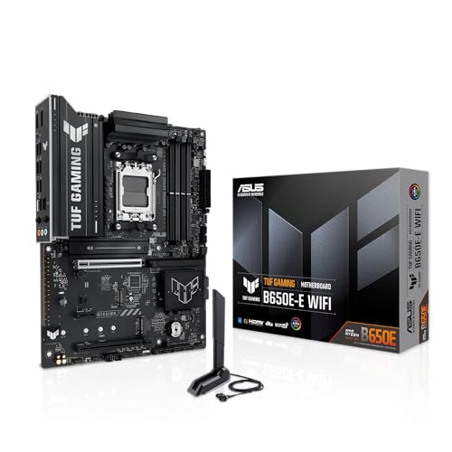
Overview: The ASUS TUF GAMING B650E-E WIFI is an ATX AM5 motherboard built for AMD Ryzen 9000, 8000, and 7000 desktop processors. Its TUF design focuses on stability, practical build features, and modern connectivity rather than flashy extras.
Performance: An 8+2+1 80A DrMOS power setup, 8-layer PCB, and large heatsinks are intended to support steady power delivery and thermal control. It also includes PCIe 5.0 readiness, one PCIe 5.0 M.2 slot, two PCIe 4.0 M.2 slots, Wi-Fi 6E, 2.5Gb LAN, and front USB 20Gbps Type-C support for fast storage, networking, and peripherals.
- Build-friendly features: PCIe Slot Q-Release, M.2 Q-Latch, Q-Antenna, Q-LED, BIOS FlashBack, and a pre-mounted I/O shield.
- Customization: Three Addressable RGB Gen 2 headers with Aura Sync support.
- Software: Two-Way AI Noise Cancellation, AI Suite 3, and ASUS DriverHub.
Considerations: The board is AM5 and DDR5 only, so older Ryzen and DDR4 parts are not compatible. It also offers just one PCIe 5.0 M.2 slot, so buyers wanting multiple Gen 5 drives will need to look higher up the stack.
Verdict: This board is a strong fit for gamers, mainstream PC builders, and upgrade-focused users who want dependable AM5 support, good expansion, and easy installation features in a well-rounded ATX platform.
What PCB Layers Do
Printed circuit boards (PCBs) use alternating layers of copper foil, fiberglass cloth impregnated with epoxy resin (prepreg), and cured core dielectrics. Standard desktop and industrial boards maintain fixed 1.6 mm nominal thickness. Adding layers does not make board thicker. Manufacturer thins internal core and prepreg layers to maintain overall z-axis profile.
Layers serve two primary roles: route electrical traces and provide continuous reference planes (ground and power). Ground planes shield high-speed traces, lower return loop inductance, prevent electromagnetic interference (EMI), and conduct thermal energy away from high-draw components.
| Stackup Metric | Standard 6-Layer Board | Standard 8-Layer Board |
|---|---|---|
| Layer Arrangement | Sig – GND – Sig/Pwr – Pwr/Sig – GND – Sig | Sig – GND – Sig – Pwr – GND – Sig – GND – Sig |
| High-Speed Routing | Microstrip outer, compromised stripline inner | Fully shielded symmetrical stripline inner |
| Reference Plane Continuity | Frequent breaks across split power planes | Unbroken solid ground planes on adjacent layers |
| Plane Copper Weight | Typically 1 oz (35 µm) to 2 oz (70 µm) | Typically 2 oz (70 µm) ground/power planes |
| Thermal Conduction (VRM) | Higher thermal resistance through core | Internal planes sink heat; drops localized ΔT by 8-15°C |
6-layer stackup forces compromise. Routing density demands inner copper layers split between voltages (12V, 5V, 3.3V, VDDQ). Inner signal traces adjacent to split power planes cross dielectric gaps. Return current diverts around gaps, loop inductance spikes, signal reflections multiply.
8-layer stackup isolates critical buses. Dedicated ground planes sandwich inner signal layers. Signal traces run as true striplines. Characteristic impedance target (50 Ω single-ended, 85 Ω or 90 Ω differential) holds within ±5% tolerance across entire trace run.
What Layer Count Means for Memory and PCIe
Signal speeds dictate physical requirements. DDR5 runs base frequencies from 4800 MT/s up to 8400+ MT/s. PCIe 5.0 runs at 32 GT/s with 16 GHz Nyquist frequency. High frequencies exhibit skin effect: current flows exclusively along trace outer perimeter. Channel loss, dielectric dissipation factor (Df), and crosstalk dominate failure modes.
Memory traces require tight matching. Data lines (DQ), strobe lines (DQS), and command/address lines (CA) operate with rise times under 100 picoseconds. On 6-layer boards, memory traces route across outer microstrip layers exposed to air. Variations in solder mask thickness alter dielectric constant (Dk 3.5 to 4.2), causing timing jitter. Trace proximity induces crosstalk exceeding -25 dB, closing eye diagram margins at operational voltages (1.1V to 1.45V VDD/VDDQ). Result: unstable memory profiles above DDR5-6400.
8-layer design routes memory lines inside board substrate between solid ground layers. Ground plane shielding cuts crosstalk below -40 dB. Stripline routing provides uniform dielectric environment (consistent Dk). Eye height remains wide, jitter drops, DDR5-7200 to DDR5-8000+ overclocks stabilize without parity errors.
PCIe 5.0 enforces -36 dB end-to-end insertion loss budget at 16 GHz. 6-layer boards exceed budget over 4 to 5-inch trace lengths due to reference plane discontinuties and substrate losses. 8-layer stackups support longer trace runs (6 to 8 inches) without requiring active retimer chips or passive redrivers, preserving PCIe 5.0 link negotiation (x16 link without dropping to Gen4 or dropping lane widths).
How to Compare Boards Without Layer Data
Vendors often omit layer count on product datasheets. Use physical and diagnostic indicators to verify construction:
- Inspect PCB Edge Markings: Manufacturers etch numbering windows on corner edge of board. Look near bottom PCIe slot or board corners. Stamped sequential numbers (“1 2 3 4 5 6” vs “1 2 3 4 5 6 7 8”) confirm total copper planes.
- Check Mounting Hole Transillumination: Shine 500+ lumen LED through unplated alignment holes or bare board edges. 6-layer boards show substantial light bleed with translucent yellow-green tint. 8-layer boards block significantly more light due to tightly spaced internal copper foils.
- Inspect Memory QVL Ratings: Motherboard manufacturer documentation specifies memory support limits. 4-DIMM boards rated strictly ≤6400 MT/s indicate 6-layer construction. 4-DIMM boards rated ≥7200 MT/s or 2-DIMM boards rated ≥8000 MT/s rely on 8-layer or 10-layer substrate.
- Analyze PCIe Slot Lane Layout: Boards offering simultaneous CPU-attached PCIe 5.0 x16 graphics slot and CPU-attached PCIe 5.0 M.2 slot without physical retimer chips present on PCB require 8 layers to route 20 high-speed differential pairs through socket breakout zone.
Choosing by Real Needs
Evaluate platform requirements, workload profiles, and operational parameters before selecting hardware:
Select 6-Layer Board When:
- Memory profile targets standard JEDEC or moderate XMP/EXPO (DDR4 3200-3600 MT/s, DDR5 5200-6000 MT/s). AMD AM5 platform running 1:1 memory controller divider (UCLK=MCLK) achieves peak latency at DDR5-6000; 6-layer traces fully satisfy this threshold.
- Bus speeds limited to PCIe 4.0 (16 GT/s), or single short-run PCIe 5.0 x16 slot direct to socket.
- System CPU pulls ≤150W continuous load. VRM thermal load remains low; additional copper plane heatsinking unnecessary.
- System cost optimization is primary engineering requirement.
Select 8-Layer Board When:
- Memory configuration runs high-frequency kits (DDR5-7200 through 8400+ MT/s) requiring stable VDD/VDDQ rail delivery above 1.40V and sub-picosecond trace matching.
- Multiple PCIe 5.0 endpoints active (Gen5 GPU slot plus one or more Gen5 NVMe storage slots across motherboard distance).
- High-draw CPUs pulling 250W, 350W peak loads (Intel Core i9 unlocked, AMD Threadripper). Dual 2 oz internal copper planes spread heat horizontally across chassis mounting posts, lowering VRM power stage temperatures by 10°C or more.
- System operates inside sealed, high-ambient (≥40°C), or continuous 24/7 workstation/industrial environments where electrical noise margin directly impacts mean time between failures (MTBF).
For related maintenance and equipment benchmarks, review our technical guides on best gaming pcs, examine multitasking gaming desktops, and compare streaming pc builds. You can also reference our analyses on vr desktop performance and high-performance gaming pcs. For industry engineering standards, consult IEEE Computer Society benchmarks.
Frequently Asked Questions
Does an 8-layer board overclock RAM better?
Yes. Stripline routing on 8-layer boards puts signal lines between ground planes. Reduces crosstalk, minimizes impedance variation, sharpens signal eye patterns. Allows higher DDR5 frequencies (7600-8400+ MT/s) at lower drive voltages with fewer parity errors. 6-layer boards hit signal degradation walls around 6400-6800 MT/s on identical memory ICs.
Where can I find a board’s layer count?
Look at PCB corners or edges under bright light. Manufacturers etch exposed copper numbers indicating layer count. If unprinted, check motherboard specification sheet for phrases like “8-layer PCB” or “server-grade PCB”. If unlisted, examine memory QVL: boards validating DDR5-7200+ on 4-slot topologies uniformly use 8 layers or more.
Do cheap boards use fewer layers?
Yes. PCB fabrication cost scales with layer count. 8-layer boards require additional lamination cycles, drill operations, prepreg material, inner layer etching passes. Budget boards utilize 4-layer or 6-layer construction to minimize Bill of Materials (BOM) cost. High-density sockets (LGA1700, AM5) make 4-layer designs rare for modern platforms; 6-layer serves as baseline minimum for low-cost motherboards.