Quick Answer: How to Test a Lawn Mower Ignition Coil
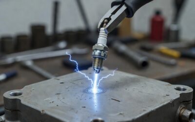
Disconnect the kill wire from the coil, remove the spark plug, ground the plug body against the engine block, and crank the engine. A strong blue spark means the coil is firing; a weak yellow/orange spark or no spark indicates coil failure. Confirm with a multimeter set to ohms: primary winding should read 0.5–3 Ω; secondary winding should read 2,500–10,000 Ω depending on brand. A reading of 0 Ω (short) or OL/infinite (open circuit) on either winding means the coil must be replaced.
Signs Your Lawn Mower Coil May Be Failing
Before pulling tools, confirm the symptom pattern matches a coil problem. Coil failure and spark plug failure share some symptoms — but the pattern below points specifically at the coil.
- No-start, no spark: The engine cranks but produces zero spark at the plug wire. A fouled plug produces the same symptom, so always swap the plug first.
- Runs then dies when hot: The engine starts cold, runs 10–20 minutes, then shuts off and refuses to restart until it cools. This is the classic signature of thermal coil failure — the coil’s internal windings expand with heat and develop an open circuit that disappears once cool, allowing it to pass a cold resistance test.
- Weak or intermittent spark: A yellow or orange spark instead of a crisp blue one. This indicates low voltage output — often a partially shorted secondary winding or incorrect armature gap.
- Misfiring or surging under load: The engine runs at idle but breaks up under cutting load, where higher electromagnetic demand exposes a marginal coil.
- New spark plug makes no difference: If a fresh plug of the correct heat range does not fix the no-spark condition, the coil or kill-wire circuit is the next logical suspect.
If your symptoms match fuel-related issues — flooding, black smoke, carburetor overflow — test the fuel system first. The coil test below is the right next step when spark is absent or weak after a confirmed good plug.
What You Need Before You Start (Tools and Safety)
Tools
- Digital multimeter with ohms (Ω) setting, or a dedicated ohmmeter
- Inline spark plug tester (optional but recommended — safer than a bare plug ground test)
- Socket set and ratchet (typically 5/16 in. or 3/8 in. for plug removal)
- Feeler gauge set (for armature gap check, Section 6)
- Insulated gloves
Safety Steps — Complete These Before Touching the Coil
- Move the mower to a hard, flat surface away from flammable material.
- Turn the ignition key to OFF or move the throttle to STOP.
- Riding mowers: Disconnect the negative (−) battery terminal to eliminate any electric-start crank during testing.
- Push mowers: Pull the spark plug wire off the plug and tuck it away before reaching near the flywheel.
- Do not drain the fuel tank for the spark test itself, but keep an extinguisher nearby. Never test for spark near open fuel.
Locating the Ignition Coil
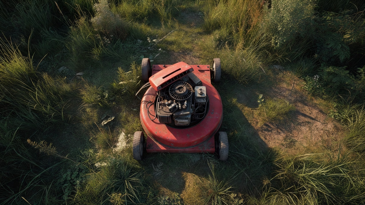
On most push mowers, the coil (also called the armature) is a small black or gray module bolted to the engine block directly adjacent to the flywheel — you will see two legs straddling the flywheel fins and a single plug wire leading to the spark plug. On riding mowers, the coil is often under the engine shroud or blower housing; remove the hood/shroud bolts and the housing to expose it. The kill wire — a thin insulated wire connecting the coil to the ignition switch or blade-brake system — attaches to a small spade or bullet connector on the coil body.
Step 1 — Perform the Spark Test (No Multimeter Needed)
The spark test tells you whether the coil is producing high-voltage output at all. It requires no meters — only a known-good spark plug and basic hand tools.
- Locate and disconnect the kill wire. Trace the thin wire from the coil body to its connector and unplug it. A grounded kill wire suppresses all spark and will produce a false coil-failure reading. This step is mandatory.
- Remove the spark plug. Use the correct socket and pull the plug. Inspect it — if the electrode is fouled, blackened, or the gap is wrong, install a new plug before continuing.
- Connect the plug to the plug wire. Push the plug wire cap firmly onto the removed plug’s terminal.
- Ground the plug body. Hold the plug’s metal threads firmly against a bare metal surface on the engine block — a bolt head or the metal shroud works. Do not hold the plug with bare fingers. Alternatively, clip an inline spark tester between the wire and a ground point, which is the safer method.
- Crank the engine. Pull the starter rope briskly (push mower) or have an assistant use the electric starter (riding mower, battery reconnected only for this step).
- Observe the spark.
- Strong blue spark: The coil is producing adequate voltage. The no-start is likely elsewhere — fuel, carburetor, valve timing, or a sheared flywheel key.
- Weak yellow or orange spark: Insufficient coil output. Proceed to the multimeter test to confirm winding condition.
- No spark at all: Either the coil is open/shorted, the kill wire is still grounded, or the flywheel magnets are damaged. Proceed to the multimeter test.
Note: Test in a shaded area or indoors with controlled lighting — a strong spark is easy to miss in direct sunlight.
Step 2 — Test the Coil with a Multimeter (Resistance/Ohm Test)
The resistance test identifies short-circuit (0 Ω) and open-circuit (OL) faults in each winding. It does not perfectly replicate the coil under operating voltage and heat, but it confirms definitive winding failures and narrows down thermal failures.
Set Up the Multimeter
Set the meter to DC resistance (Ω). If the meter is not auto-ranging, start at the 200 Ω range for primary and switch to the 20 kΩ range for secondary.
Primary Winding Test
- Locate the two primary terminals on the coil body. On most small-engine coils, these are the kill-wire spade terminal and the ground leg (one of the mounting bolts or a dedicated ground lug).
- Place one probe on the kill-wire terminal and the second probe on the coil’s ground point (mounting bolt or ground lug).
- Read the meter.
- Pass: 0.5–3 Ω (varies by brand — see table below)
- Fail — short: 0 Ω or near-zero — internal short between windings
- Fail — open: OL or infinite — broken primary winding wire
Secondary Winding Test
- Place one probe inside the spark plug wire boot (contact the metal terminal inside) and the second probe on the coil’s ground lug or engine block.
- Read the meter.
- Pass: 2,500–10,000 Ω depending on brand (see table below)
- Fail — short: Reads well below the brand minimum — windings are shorting internally
- Fail — open: OL — the secondary winding or the plug wire itself has an internal break
- If the secondary reads OL, test the plug wire alone by probing both ends. A broken wire gives OL; replace the wire before condemning the coil.
Thermal failure caveat: A coil that only fails when hot can pass both winding tests at room temperature. If your symptom is run-then-die and both cold tests pass, use a heat gun to warm the coil body to operating temperature (approximately 150–180 °F / 65–82 °C) and retest immediately. A reading that shifts to OL or 0 Ω when warm confirms thermal failure.
Ignition Coil Resistance Specs by Brand (Ohm Range Reference Table)
OEM resistance specifications vary significantly across manufacturers. Use the table below to evaluate your multimeter readings. When a specific engine model number is available, cross-reference it against the OEM service manual for the exact figure — the ranges below cover the most common consumer engine series.
| Brand | Primary Winding (Ω) | Secondary Winding (Ω) | Notes |
|---|---|---|---|
| Briggs & Stratton | 0.9–1.5 Ω | 2,500–3,500 Ω | Magnetron® electronic coils. Verify against Model/Type/Code label. Secondary spec sourced from Briggs & Stratton Repair Manual MS-6225. |
| Kohler | 1.0–3.0 Ω | 1,000–2,000 Ω | Covers Command and Courage series. Kohler service manuals note secondary may read as low as 900 Ω on some Command Pro variants. Always confirm against engine-specific TP document. |
| Kawasaki | 0.1–1.0 Ω | 6,000–12,000 Ω | FH, FR, FS series. Kawasaki service manuals specify a wide secondary range; readings near 12 kΩ are normal for some FH series. Low primary resistance is normal for Kawasaki solid-state coils. |
| Tecumseh | 0.5–2.5 Ω | 3,000–6,000 Ω | Covers most 3–10 HP Tecumseh/LCT units. Archived Tecumseh service manuals (Form No. 694055) list secondary spec at approximately 3 kΩ–5 kΩ for HMSK and HSK series. |
| Honda | 0.1–1.0 Ω | 6,500–10,000 Ω | GCV and GX series. Honda shop manuals specify primary at approximately 0.1–0.5 Ω on GCV160; secondary typically 6.5–8.5 kΩ. Source: Honda GCV160 and GX160 Shop Manuals. |
If your engine brand is not listed, the OEM service manual is the authoritative source. Many manufacturers publish free PDF service manuals on their support portals. Enter the engine model and type numbers (stamped on the engine block) into the manufacturer’s parts lookup to find the correct manual.
How to Check the Armature Air Gap (and Why It Affects the Test)
The armature air gap is the distance between the coil’s two legs and the flywheel magnets. If this gap is too wide, the magnetic field coupling is too weak to induce adequate voltage — producing the same weak-spark symptom as a failing coil. Check the gap before condemning a coil that passes the resistance test.
Standard Air Gap Ranges by Brand
- Briggs & Stratton: 0.006–0.010 in. (0.15–0.25 mm)
- Kohler: 0.008–0.012 in. (0.20–0.30 mm)
- Kawasaki: 0.006–0.014 in. (0.15–0.35 mm)
- Tecumseh: 0.0125 in. (0.32 mm) — most series use a fixed spec
- Honda: 0.008–0.012 in. (0.20–0.30 mm)
These ranges represent typical values for common consumer engine series. Confirm against the specific engine service manual.
How to Set the Armature Gap
- Loosen the two coil mounting bolts until the coil can slide freely.
- Rotate the flywheel by hand until the magnet is directly under the coil legs.
- Slide a feeler gauge of the correct thickness between the flywheel and both coil legs simultaneously.
- Press the coil legs down against the feeler gauge and snug the mounting bolts finger-tight.
- Tighten the bolts to spec (typically 25–40 in-lb), then slide the feeler gauge out. Rotate the flywheel — the gauge should slide out with slight resistance. If the coil drags the flywheel, the gap is too tight; re-loosen and reset.
Also check the flywheel key. A sheared or partially sheared Woodruff key shifts ignition timing and produces a no-start or backfire that mimics coil failure. Inspect the key whenever the flywheel is exposed during the coil gap procedure. Replace any key that shows deformation — it is a inexpensive part and a common failure after blade strikes.
Replace or Reuse? How to Read Your Test Results
Use this decision matrix to reach a final verdict based on your test results.
| Spark Test | Primary Ohm Test | Secondary Ohm Test | Verdict |
|---|---|---|---|
| Strong blue spark | Pass | Pass | Coil is good. Investigate fuel system, carburetor, valve train, or sheared flywheel key. |
| No spark | Pass | Pass | Check kill wire and armature gap first. A grounded kill-wire circuit (faulty switch, safety interlock, or pinched wire) suppresses spark without damaging the coil. Set gap and retest. |
| Weak/yellow spark | Pass | Pass (but near low limit) | Check armature gap and flywheel magnets. Reset gap; inspect flywheel magnets for cracks or oil contamination. If gap and magnets are correct and spark remains weak, replace coil. |
| No spark or weak spark | 0 Ω or OL | Any | Replace the coil. Primary winding failure is confirmed. |
| No spark or weak spark | Pass | 0 Ω or OL | Replace the coil (or plug wire if wire tests open independently). |
| Passes cold, fails when hot | Pass cold | Pass cold / OL warm | Replace the coil. Thermal failure confirmed. Cold resistance tests do not catch this — use the heat-gun retest method described in Step 2. |
Cost and DIY Feasibility
Replacement ignition coils for common Briggs & Stratton, Kohler, and Honda engines typically cost $15–$45 for aftermarket units, and $40–$90 for OEM parts. Installation on a push mower — loosen two bolts, transfer plug wire, set gap — takes 20–30 minutes with basic hand tools. Riding mower coil replacement adds shroud removal but remains a straightforward DIY task. Labor at a small engine shop typically runs $60–$100/hour; the total repair cost often exceeds the coil cost alone, making self-diagnosis and DIY replacement practical for most owners.
Frequently Asked Questions
Can a lawn mower ignition coil fail only when hot and pass a cold test?
Yes. Thermal failure is a documented failure mode in solid-state ignition coils. The internal epoxy and winding insulation degrade over time, creating an intermittent open circuit that appears only at operating temperature. A coil that passes both resistance tests cold but causes a run-then-die symptom should be retested immediately after warming with a heat gun. If resistance shifts to OL when warm, replace the coil.
My mower has spark but still won’t start — does that mean the coil is fine?
A visible spark confirms the coil is producing output, but spark quality matters. A strong blue spark with the plug wire held 1/4 in. from ground is sufficient; a weak spark that only fires when the plug is touching the block may not ignite the air-fuel mixture under compression. If spark quality passes and the engine still won’t start, move to fuel delivery — check for fuel at the carburetor, verify choke operation, and inspect the carburetor float and jets.
Do I need to disconnect the kill wire before testing for spark?
Yes — this step is mandatory. The kill wire grounds the coil’s primary circuit to stop the engine. A faulty ignition switch, a stuck safety interlock (seat switch, blade-brake switch on riding mowers), or a pinched kill wire can hold the coil permanently grounded, producing zero spark despite a perfectly functional coil. Disconnecting the kill wire isolates the coil from the rest of the circuit and eliminates false failures.
What is the difference between testing a push mower coil and a riding mower coil?
The electrical test procedure is identical. The practical differences are access and safety. On a push mower, the coil is exposed after removing the engine shroud — typically two to four bolts. On a riding mower, the coil is under the engine blower housing, which may require removing the hood, battery cover, and several shroud panels. Riding mowers also have multiple safety interlock switches (seat, PTO, brake) wired into the kill circuit; any one of them can suppress spark, so tracing the kill wire fully before condemning the coil is especially important on riding equipment.