Quick Answer
Safe motherboard VRM temperature sits below 85°C under sustained load. Most quality MOSFETs are rated to 105 to 125°C junction temperature, but thermal throttling and lifespan degradation begin aggressively above 90°C. Add heatsinks, improve airflow, or reduce CPU overclock voltage if readings exceed that threshold consistently.

Pros
- Built for Intel Xeon W-3400 and W-2400 processors on the LGA 4677 platform.
- Five PCIe 5.0 x16 slots offer unusually strong expansion for a workstation motherboard.
- Dual 10G plus 2.5G Ethernet provides high-speed wired networking options.
- Thermal design includes substantial heatsinks, M.2 cooling, and multiple fan headers.
Cons
- Compatibility is limited to the Xeon W-3400 and W-2400 platform, so it is not suitable for mainstream Intel CPUs.
- Only two PCIe 4.0 M.2 slots are listed, which may be modest for storage-heavy builds.
- Wireless networking is not specified in the manufacturer listing.
Overview: The ASUS Pro WS W790-ACE is a workstation motherboard built for Intel Xeon W-3400 and W-2400 processors on the LGA 4677 platform. Its CEB form factor and heavy-duty heatsinks give it a serious, professional appearance suited to high-end builds.
Performance & features: This board focuses on expansion and throughput, with five PCIe 5.0 x16 slots, DDR5 RDIMM support, dual 10G and 2.5G Ethernet, and front and rear USB 3.2 Gen 2x2 Type-C. It also includes 12+1+1 power stages, seven 4-pin PWM fan headers, a Water pump+ header, and ASUS Control Center Express support for advanced management.
Drawbacks & considerations: The platform is highly specialized, so it only makes sense for users who are committed to the Xeon W-3400 or W-2400 family. The manufacturer listing also lists just two PCIe 4.0 M.2 slots, and wireless connectivity is not specified.
Verdict: This is a strong choice for professionals who need workstation-grade expansion, fast wired networking, and robust cooling support. It is less suitable for general desktop users, but it should deliver real value in creator, engineering, and server-adjacent builds.

Pros
- Excellent platform support for AMD Threadripper PRO 7000 WX and Threadripper 7000 CPUs.
- Strong power delivery and cooling design for sustained workstation workloads.
- Broad connectivity with PCIe 5.0, WiFi 7, dual LAN, and multiple high-speed storage options.
- ECC R-DIMM DDR5 support is ideal for stability-focused professional systems.
Cons
- Limited to the AMD sTR5 platform, so it is not compatible with mainstream desktop CPUs.
- Advanced workstation features such as IPMI depend on expansion card support rather than being fully built in.
- Its feature set is likely more than most everyday users or gaming-only builds will need.
Overview and design: The ASUS Pro WS TRX50-SAGE WIFI CEB is a workstation-class motherboard built for AMD Ryzen Threadripper PRO 7000 WX-Series and Threadripper 7000 Series processors on the sTR5 platform. It is clearly aimed at professional builders who need a stable, high-expansion foundation rather than a typical consumer desktop board.
Performance and key features: The board combines 36 power stages, dual 8-pin CPU power connectors, and substantial VRM and M.2 cooling to support demanding, long-duration workloads. It also offers ECC R-DIMM DDR5 support up to 1TB, three PCIe 5.0 x16 slots, three M.2 slots, SlimSAS NVMe support, WiFi 7, and both 10 Gb and 2.5 Gb LAN for fast networking and storage performance.
Drawbacks and considerations: This is a specialized platform, so compatibility is limited to AMD sTR5 processors. Its server-inspired features, including IPMI support through expansion cards, are useful for professional environments but may be unnecessary for many users. It is best suited to builders who can use its full feature set.
Verdict: The ASUS Pro WS TRX50-SAGE WIFI CEB makes the most sense for creators, engineers, and workstation users building around Threadripper PRO 7000 hardware. If you need high memory capacity, strong expansion, and pro-grade connectivity, it is a compelling choice. For mainstream PC builds, it is more motherboard than most users will need.

Pros
- Strong power delivery and premium components suit high-end Intel Core Ultra Series 2 builds.
- Six total M.2 slots offer excellent storage expansion for fast SSD setups.
- WiFi 7 plus 5Gb Ethernet provide modern, high-speed networking options.
- Thunderbolt 4 and multiple USB Type-C ports make it well equipped for peripherals and external storage.
Cons
- Requires an Intel LGA 1851 processor, so it is not compatible with older Intel CPUs.
- The ATX form factor may not fit compact small-form-factor cases.
- Its enthusiast-focused feature set may be more than some mainstream users need.
Overview: The ASUS ROG Maximus Z890 Apex is a premium ATX motherboard built for Intel Core Ultra processors in the LGA 1851 socket. It uses a heavy-duty power design, large heatsinks, and a feature set aimed at high-performance desktops, AI-ready systems, and serious enthusiasts.
Performance and Features: This board stands out for its 22+1+2+2 power stages, DDR5 support, PCIe 5.0 expansion, and broad storage options. With three PCIe 5.0 M.2 slots on the board, two additional M.2 slots on the ROG DIMM.2 card, WiFi 7, Realtek 5Gb Ethernet, and dual Thunderbolt 4 ports, it is well equipped for fast storage, low-latency networking, and demanding peripherals.
Drawbacks and Considerations: The main limitation is compatibility, since it only works with Intel LGA 1851 processors. Its ATX size also requires a full-size case, and many of its tuning and connectivity features may be unnecessary for users building a simpler mainstream PC.
Verdict: This motherboard is best suited to enthusiasts, overclockers, and advanced builders who want premium power delivery, strong expansion, and modern connectivity. It offers a lot of headroom, but users who do not need high-end storage, networking, or tuning tools may find a more modest board to be a better value.

Pros
- Built for the sTRX4 platform and 3rd Gen Threadripper CPUs, which suits serious workstation use.
- Strong power delivery design is well matched to sustained multi-core workloads.
- Triple PCIe 4.0 M.2 support offers excellent fast-storage expansion.
- Thermal design is more extensive than typical consumer boards, with multiple heatsinks and hybrid fan headers.
Cons
- Only compatible with AMD sTRX4 Threadripper processors, so it is not a universal motherboard choice.
- The listed networking is Intel Gigabit Ethernet, with no higher-speed multi-gig or Wi-Fi features specified.
- Its feature set is aimed at high-end creator systems, so it may be more than most general-purpose users need.
Overview: The ASUS Prime TRX40-Pro S is an ATX motherboard built for the AMD sTRX4 platform and 3rd Gen Ryzen Threadripper processors. It is clearly aimed at content creation and workstation builds, with a premium component layout designed for demanding users.
Performance: With 16 power stages, ProCool II connectors, premium chokes, and capacitors, the board is designed to provide stable power for heavy multi-core workloads. It also includes multiple heatsinks, an active chipset cooling solution, and triple PCIe 4.0 M.2 slots for fast storage expansion.
Considerations: This is a specialized board, so compatibility is limited to sTRX4 Threadripper CPUs. The manufacturer specifications list Intel Gigabit Ethernet, and no Wi-Fi or higher-speed multi-gig networking is specified.
Verdict: For users building a high-end creator PC or workstation around a 3rd Gen Threadripper CPU, the Prime TRX40-Pro S offers the power delivery, thermal design, and expansion expected from a premium platform. It is best for buyers who will make full use of its workstation-focused features.

Pros
- Built for AMD Threadripper PRO 7000 platforms, which suits high-end workstation builds.
- Strong connectivity selection with USB4, PCIe 5.0, dual LAN, and Wi-Fi 7.
- Cooling-focused design includes VRM Thermal Armor and M.2 Thermal Guard.
- EZ-Latch hardware simplifies installing and removing compatible PCIe 5.0 and M.2 devices.
Cons
- Only compatible with AMD sTR5 and Threadripper PRO 7000 Series CPUs, so it is not suitable for mainstream builds.
- The E-ATX form factor requires a large case and may limit chassis compatibility.
- Its feature set is aimed at premium workstation users, which may be more than some builders need.
Overview: The GIGABYTE TRX50 AERO D is an E-ATX workstation motherboard built for AMD sTR5 and Ryzen Threadripper PRO 7000 Series processors. Its 16+8+4 phase digital VRM, VRM Thermal Armor, and M.2 Thermal Guard give it a clear focus on sustained professional workloads.
Performance and features: This board is designed for fast storage, strong memory support, and modern connectivity. It offers four DDR5 SMD R-DIMM slots with AMD EXPO and Intel XMP support, PCIe 5.0 expansion, dual USB4 Type-C, and high-speed networking through 10GbE, 2.5GbE, and Wi-Fi 7.
Drawbacks and considerations: The biggest limitation is compatibility, since it is only for sTR5 Threadripper PRO 7000 CPUs. Its E-ATX size also means you will need a roomy case, and the workstation feature set may be excessive for users who do not need this level of expandability.
Verdict: For creators, engineers, and advanced users building a Threadripper PRO workstation, the TRX50 AERO D delivers a strong mix of power delivery, fast I/O, and premium networking. If you want a smaller or more mainstream platform, a different motherboard class will be a better fit.
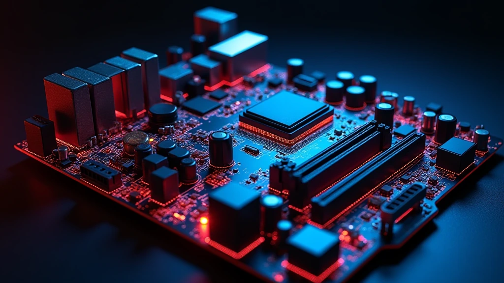
The Voltage Regulator Module is the single most thermally stressed silicon on your motherboard, yet it receives a fraction of the cooling attention given to the CPU or GPU. Every watt your processor pulls passes through the VRM first, converted from the 12 V ATX rail down to the 0.9 to 1.5 V the CPU cores actually consume. That conversion is never perfectly efficient, and the lost energy becomes heat concentrated in a handful of MOSFETs, inductors, and PWM controller ICs packed into a few square centimetres of PCB. Understanding motherboard VRM temperature, what drives it, how to measure it, and when it becomes dangerous, is prerequisite knowledge for anyone running a modern high-TDP processor, attempting an overclock, or building a system expected to run 24/7 under production workloads. This guide covers the full engineering picture, from phase-count physics to real corrective action.
What a VRM Actually Does and Why It Gets Hot
The Buck Converter Fundamentals
A VRM is a synchronous buck converter , a switching power supply that steps voltage down by rapidly toggling high-side and low-side MOSFETs at frequencies typically between 300 kHz and 1 MHz. An inductor and output capacitors smooth the resulting pulse-width-modulated waveform into the near-DC voltage the CPU requires. Efficiency on a modern digital VRM sits in the 87, 94% range depending on load and design quality. At 200 W CPU load and 90% efficiency, roughly 22 W is dissipated as heat across the MOSFET array. That number scales linearly with CPU TDP , a 320 W Intel Core Ultra 9 285K at full AVX-512 load dumps well over 35 W into the VRM thermal mass before airflow removes any of it. To compare alternative configurations, check our hands-on review of mix nvme and sata ssd.
Power Phases: Parallelism as a Thermal Strategy
Adding phases distributes the current load. A single-phase VRM handling 200 A faces a single inductor and MOSFET pair carrying the full current, and resistive losses scale with the square of current (P = Iu00b2R). Split that across 16 phases and each phase carries ~12.5 A, reducing per-phase resistive loss by a factor of 256/16 = 16u00d7. This is why flagship boards for the AMD Ryzen 5 9600X vs Intel Core Ultra 5 245K generation ship with 16 to 20 true power phases rather than doubler-multiplied pseudo-phases, real phase count directly determines steady-state VRM temperature at high current draw.
Doublers, Teasers, and Marketing Phase Counts
Phase doublers (Intersil ISL6617, On Semi NCP81274) split a single PWM control signal into two interleaved signals driving two MOSFET pairs. Electrically this halves ripple current per inductor but does not halve per-MOSFET current the way a true additional controller channel does. A board marketed as “16+2 phase” may use an 8-channel PWM controller with doublers, delivering 16 switching nodes but not 16 independent current paths. Under sustained heavy load this distinction matters: true multi-phase designs run cooler because the gate-drive losses and conduction losses are distributed across genuinely independent silicon. When comparing platform options like the ASUS ROG Maximus Z890 Hero vs MSI MEG Z890 ACE, examine the PWM controller datasheet, not just the headline phase number on the product page.
Motherboard VRM Temperature: Thresholds, Ratings, and the Real Danger Zone
MOSFET Junction vs. Sensor Temperature
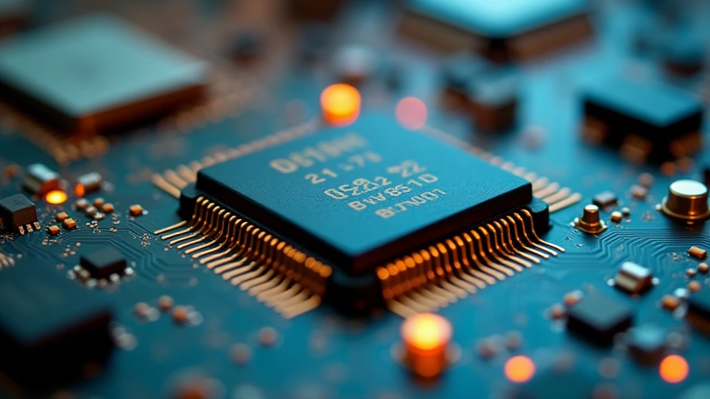
The temperature sensor embedded on most motherboards measures the PCB surface near the VRM or the heatsink baseplate, not the MOSFET junction itself. Junction-to-case thermal resistance (Ru03b8jc) for a modern DrMOS device (Renesas RAA220075, Vishay SiC654) is typically 0.4 to 0.8°C/W. At 2 W dissipation per phase with Ru03b8jc = 0.6°C/W, the junction runs 1.2°C above the case. Add case-to-heatsink interface resistance and the sensor may read 15 to 25°C below actual junction temperature under poor cooling conditions. Always interpret VRM sensor readings conservatively, if the sensor says 90°C, junction temperature is plausibly 100 to 110°C.
Official Ratings vs. Practical Operational Limits
| VRM Temperature Range (Sensor Reading) | Status | Typical Effect | Action Required |
|---|---|---|---|
| Below 60°C | Excellent | Full efficiency, maximum component longevity | None |
| 60°C – 75°C | Normal | Acceptable for mid-range boards under full load | Monitor; verify heatsink contact |
| 75°C – 90°C | Elevated | Acceptable on flagship boards; marginal on budget hardware; minor longevity impact | Improve airflow; add VRM heatsink |
| 90°C – 105°C | Critical | Thermal throttle activation likely; accelerated electromigration in MOSFET dies; capacitor ESR degradation | Immediate intervention, heatsink, airflow, voltage reduction |
| Above 105°C | Dangerous | OVP/OTP protection triggers; system shutdown or instability; permanent silicon degradation risk | Stop stress testing immediately; diagnose root cause before next boot |
Thermal Throttling Mechanics
When the PWM controller’s internal over-temperature protection (OTP) threshold is crossed , typically configured by board firmware between 105°C and 120°C , it reduces switching duty cycle, starving the CPU of current. The CPU package power drops, temperature falls, protection disengages, power recovers, and the cycle repeats. This manifests as stuttering in games, inconsistent benchmark scores, or erratic CPU frequency in HWiNFO64’s frequency graph. It is frequently misdiagnosed as a CPU cooling problem because CPU temperatures simultaneously drop , the thermal reduction is coming from the VRM layer below the OS’s visibility. Users looking for related component recommendations can explore our pcie riser cable signal degradation breakdown.
How to Monitor Motherboard VRM Temperature Accurately
Software Tools and Sensor Access
HWiNFO64 is the gold standard, it queries the Super I/O chip (Nuvoton NCT6798D, ITE IT8792E) or embedded controller directly and exposes VRM/MOS temperature sensors that most other tools miss. Open HWiNFO64 in Sensors-only mode and look for entries labelled VRM MOS, T_VRM, PCH Temperature, or CPU VCore Phase Temp depending on board vendor naming conventions. AIDA64 Extreme also exposes these sensors and includes a stress test that drives sustained CPU load, useful for observing VRM temperature at realistic workloads. CPU-Z alone does not read VRM thermal sensors. MSI Afterburner reads GPU VRM sensors but not CPU motherboard VRM sensors unless paired with HWiNFO64’s shared memory export.
Stress Test Protocol for Accurate Baseline Measurement
Run a CPU-only stress test for a minimum of 20 minutes to allow VRM thermal mass to reach steady state , MOSFET packages have non-trivial thermal capacitance and early readings are optimistic. OCCT’s CPU:LINPACK test with AVX-capable enabled produces near-worst-case current draw. Prime95 Small FFTs with AVX enabled is comparable. Cinebench R23 nT produces realistic gaming-adjacent loads. Record the peak sensor reading, not the average , transient spikes during cache flush cycles can exceed steady state by 5, 8°C and are the temperatures that stress MOSFET gate oxides most. Ambient temperature matters: add approximately 1°C of VRM reading for every 1°C rise in case intake temperature. Before finalizing equipment decisions, refer to our comprehensive thunderbolt 4 vs usb4 difference comparison.
Factors That Drive VRM Temperature Higher Than Expected
CPU TDP and Voltage
VRM heat scales directly with CPU package power. A processor running at 1.40 V under load versus 1.25 V at the same frequency represents a 12% higher voltage, and since dynamic power scales as Vu00b2, this is a ~26% increase in CPU switching power, a proportional increase in current demand, and a corresponding jump in Iu00b2R losses across every phase inductor and MOSFET. For overclocking-heavy platforms tracked in our desktop CPU benchmarks & reviews, VRM temperature is as important a stability ceiling as CPU junction temperature.
Case Airflow and VRM Heatsink Design
Most mid-range and budget ATX boards ship with a passive VRM heatsink, a small aluminium block with minimal fin density relying on natural convection or incidental airflow from the CPU cooler fan. In a case with poor front-to-rear airflow, this convection is nearly zero at idle and inadequate under load. A 120 mm or 140 mm case fan positioned to exhaust toward the rear of the motherboard (near the VRM array at the top of the board) can reduce steady-state VRM temperature by 10 to 20°C. Tower air coolers with fans directing airflow toward the rear panel inherently assist VRM cooling; AIO liquid coolers mounted as front intakes do not, and frequently leave the VRM in stagnant hot air.
Heatsink Contact Quality
Factory thermal pads on VRM heatsinks are frequently 1.0 to 1.5 W/mK conductivity, functional but not optimal. Aftermarket thermal pads at 6 to 12 W/mK (Thermal Grizzly Minus Pad 8, Gelid GP-Extreme) can reduce heatsink-to-MOSFET interface resistance by 60 to 70%, directly translating to lower sensor readings. Re-seating the VRM heatsink with fresh high-conductivity pads cut to exact MOSFET footprint dimensions is one of the highest ROI cooling interventions available, it costs under $15 and requires 20 minutes of work.
PCIe Slot Electrical Interaction
High-power discrete GPUs drawing 300 to 400 W create secondary thermal plumes that interact with motherboard temperature zones. While the GPU’s own power delivery is separate, the PCIe slot’s 75 W delivery path runs through the motherboard PCB trace network governed by the PCI-SIG PCIe Specification Standard. A board running a GPU with an aggressive power target alongside a high-TDP CPU must manage both thermal zones simultaneously, relevant when pairing a high-end CPU with something like a GPU discussed in our Radeon RX 9060 XT 8GB vs 16GB comparison or evaluating systems from the graphics card tests & GPU guides section.
Reducing Motherboard VRM Temperature: Ranked Interventions
Tier 1, Zero-Cost Airflow Optimisation
Reposition existing case fans to maximise front-to-rear airflow. Ensure no cables obstruct the path between the front intake and rear exhaust. Remove dust filters and clean accumulated dust from the VRM heatsink fins, even 1 mm of dust acts as a thermal blanket. Verify the CPU cooler fan is spinning at speed during load; a fan that ramps too conservatively leaves the VRM in dead air. These changes cost nothing and routinely drop VRM temps by 8 to 15°C.
Tier 2, Heatsink Pad Replacement
Remove the VRM heatsink (typically 2 to 4 screws), clean old thermal interface material with isopropyl alcohol, cut replacement pads (6 W/mK or higher) to match each MOSFET and driver IC footprint, reinstall with uniform pressure. This is effective on all board tiers and is particularly impactful on boards where the factory pad has hardened and lost contact conformity over 18+ months of thermal cycling.
Tier 3, Active VRM Cooling Addition
Small 40 mm or 60 mm fans zip-tied or bracket-mounted above the VRM heatsink, connected to a motherboard header in PWM mode, provide forced convection where passive cooling fails. Noctua NF-A4x20 or equivalent quality fans at 2,000 to 5,000 RPM over a VRM heatsink drop temperatures by 20 to 35°C in low-airflow scenarios. This approach works especially well in compact mATX or ITX builds where case airflow cannot be rerouted.
Tier 4, Voltage and Power Limit Reduction
Reduce CPU core voltage in BIOS by 20 to 50 mV increments and re-test stability. For Intel platforms, setting Package Power Limit 1 (PL1) to the processor’s rated TDP (rather than the board’s default unlimited value) caps sustained current draw and directly caps sustained VRM temperature. For AMD platforms, setting PPT (Package Power Tracking) limit to nominal wattage achieves the same result. Performance loss at stock-adjacent voltages is typically under 3 to 5% in real workloads while VRM temperatures drop 10 to 25°C.
Final Diagnostic Verdict & Maintenance Checklist
Motherboard VRM temperature is a first-order stability and longevity variable, not a secondary concern. A board with a high-quality 16-phase true-phase design, good heatsink contact, and adequate airflow will sustain peak CPU loads indefinitely at under 80°C. A budget 6-phase board with a vestigial heatsink and no case airflow will hit 100°C under the same CPU and begin degrading within months. The following checklist covers every actionable diagnostic step in priority order:
- Install HWiNFO64 and identify the VRM/MOS temperature sensor by name, confirm it is updating and not a static default value.
- Run a 20-minute sustained CPU stress test (OCCT LINPACK AVX or Prime95 Small FFTs) and record peak VRM sensor temperature.
- If peak VRM temperature exceeds 85°C, check case fan configuration and optimise airflow before any other intervention.
- If VRM temperature exceeds 90°C after airflow fix, remove the VRM heatsink and inspect thermal pad condition; replace with 6 W/mK pads.
- If VRM temperature still exceeds 90°C, add active cooling (40 to 60 mm fan on a PWM header above the VRM heatsink).
- If VRM temperature exceeds 95°C with active cooling, reduce CPU voltage or apply package power limits in BIOS; the board’s phase count or MOSFET rating is the binding constraint.
- If the system throttles, crashes, or reboots under load, cross-reference VRM temperature log timestamps with crash timestamps in HWiNFO64’s session log before assuming CPU or RAM fault.
- Perform annual VRM heatsink maintenance, remove, clean, replace thermal pads, and clear dust from heatsink fins every 12 months in dusty environments, every 18 to 24 months in clean cases.
- Verify board phase count against CPU TDP before purchase, a 253 W PL2 processor requires a board with at minimum 12 true phases and a substantive heatsink; pairing it with a 6-phase entry board is an engineering mismatch regardless of socket compatibility.
- Record baseline VRM temperatures after a clean build and compare against readings six months later, a rising trend at identical load indicates thermal interface degradation and pre-empts emergency intervention.
The VRM is not a set-and-forget component. Its thermal health determines whether the CPU beneath it reaches its performance ceiling or throttles short of it, and whether the board survives three years of heavy use or begins failing at eighteen months. Measure it, understand the numbers, and treat 85°C as the ceiling worth defending.
Heat and Power Safety Notes
Voltage regulator modules convert power for the processor and can run warm under sustained load. Guidance on electrical safety around hardware is at American National Standards Institute (ANSI); read it before adding airflow or changing fan settings.