Quick Answer
CPU delidding removes the integrated heat spreader (IHS) to replace degraded stock thermal interface material with liquid metal or high-performance paste, cutting junction temperatures by 10–30°C on Intel processors. The procedure voids warranties, risks permanent die damage, and demands precision tooling — but delivers measurable, sustained thermal headroom for enthusiast overclocking.

Pros
- 14-core hybrid architecture with 6 P-cores and 8 E-cores
- Unlocked clock speeds up to a rated 5.2 GHz
- Equipped with 26MB cache for responsive processing
- Supports modern PCIe 5.0 and 4.0 standards
- Compatible with Intel 800 series motherboards
Cons
- Requires a dedicated discrete graphics card
- Does not include a cooling solution

Pros
- 24 cores (8 P-cores, 16 E-cores) and 32 threads for intense multitasking
- Advertised maximum clock speed reaching up to 6.0 GHz
- Broad compatibility with both DDR4 and DDR5 memory platforms
- Features integrated Intel UHD Graphics 770
Cons
- Requires a potential BIOS update for Intel 600-series motherboards

Pros
- High 5.4 GHz max boost is well suited to gaming workloads.
- Unlocked multiplier gives experienced users tuning headroom.
- AM5 and DDR5 support align with current-generation desktop platforms.
- 6-core, 12-thread layout is practical for gaming and general use.
Cons
- Cooler is not included, so buyers must plan for separate cooling.
- Requires an AM5 motherboard and DDR5 memory, which limits drop-in upgrades for older systems.
- 6 cores may be less ideal for heavy content creation or workstation tasks than higher-core CPUs.
Overview: The AMD Ryzen 5 9600X is a 6-core, 12-thread unlocked desktop processor built on the Zen 5 architecture. It is aimed at users who want a fast, modern CPU for an AM5-based gaming PC or a responsive everyday desktop build.
Performance and features: With a 5.4 GHz max boost, 38 MB cache, and DDR5-5600 support, this processor is positioned for strong gaming responsiveness and smooth multitasking. Select AM5 motherboards can also provide PCIe 5.0 support, which adds future-ready flexibility for compatible components.
Drawbacks and considerations: The main limitation is that a cooler is not included, so total build cost can rise once cooling is added. It also depends on the AM5 platform and DDR5 memory, which makes it less convenient for older AMD or Intel system upgrades.
Verdict: This CPU makes the most sense for gamers and PC builders who want a fast, unlocked Ryzen chip for a current-generation AM5 system. If you want a straightforward upgrade path and value high boost clocks over bundled extras, the Ryzen 5 9600X is a strong fit.
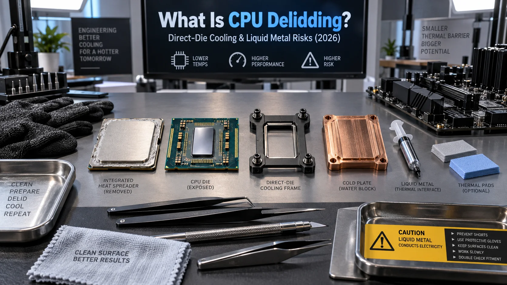
CPU delidding is the process of mechanically separating a processor’s integrated heat spreader from the silicon die beneath it, then replacing the factory-applied thermal interface material (TIM) with a superior compound — most commonly liquid metal alloys such as Conductonaut or Thermal Grizzly’s Conductonaut Extreme. The technique has existed since the Socket 775 era but gained widespread attention when Intel’s Skylake and Kaby Lake generations shipped with low-grade polymer TIM between die and IHS, creating a thermal bottleneck that undermined expensive cooling hardware. In 2026, with processors like Intel Core Ultra 200-series and AMD’s Zen 5 architectures pushing power densities past 200W on a shrinking silicon footprint, understanding the physics, tooling, and failure modes of delidding has never been more consequential for the serious builder. This guide covers every layer of the process — mechanical, chemical, thermal, and electrical — so you can make an informed decision before touching a blade to your chip.
The Physics Behind IHS Thermal Bottlenecks
Why the Stock TIM Fails at High Power Density
Intel has historically used a polymer-based TIM between the die and IHS on mainstream desktop processors — a material with thermal conductivity typically in the range of 4–8 W/mu00b7K. That figure sounds reasonable in isolation, but the bond-line thickness (BLT) imposed by mass-production soldering tolerances can reach 50–100 u00b5m, which multiplies thermal resistance dramatically. At 150W continuous package power, even a modest 0.05°Cu00b7cmu00b2/W increase in interface resistance translates to a 5–10°C delta at the junction. On a 10mm u00d7 10mm die footprint, that delta compounds further because heat flux density rises as die area shrinks. To evaluate matched hardware tolerances, consult our detailed overview of custom cpu fan curve.
AMD took a different approach on Ryzen: AM4 and AM5 processors are soldered directly between die and IHS using indium-based solder (STIM), achieving thermal conductivity of 35–80 W/mu00b7K. This is why delidding an AMD Ryzen processor rarely delivers the same dramatic gains as delidding a polymer-TIM Intel chip — the factory interface is already close to optimal. For a detailed silicon-level comparison of AMD and Intel thermal architectures, see our AMD Ryzen 5 9600X vs Intel Core Ultra 5 245K breakdown, which examines real-world thermal throttling behavior under sustained cinebench loads.
Die-to-IHS Gap and Contact Pressure Variables
Beyond TIM conductivity, physical contact geometry matters. The IHS is attached to the substrate via adhesive sealant — typically a silicone RTV compound applied at the four corners and sometimes along edges. This adhesive sets the IHS height relative to the die surface, creating a controlled gap. Manufacturing variance in this gap means two units of the same SKU can have meaningfully different factory thermal performance, which partly explains the well-documented “silicon lottery” behavior. When you delid, you gain control over this gap: direct-die cooling eliminates it entirely by mounting the cooler block directly onto the die surface, while re-lidding with a custom copper IHS and liquid metal closes the gap to near-zero BLT.
Tooling, Methods, and Mechanical Risk Assessment
Delid Tools vs. Vice Method vs. Razor Blade
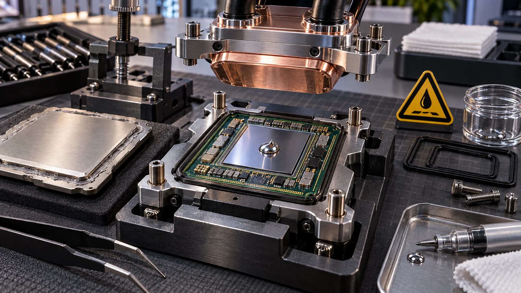
Three primary delidding methods exist, each with a distinct risk-to-precision tradeoff. The razor blade method — sliding a thin blade under the IHS edge to cut the RTV adhesive bead — is the oldest technique and carries the highest risk of slipping and physically cracking the die or severing substrate traces. It requires no specialized hardware but demands extremely steady hands and a fully supported chip. The vice/clamp method uses two aluminum or acetal blocks — one static, one driven by a thumb screw — to apply controlled lateral shear force that pops the IHS off the adhesive. It is safer than the blade method but still generates unpredictable peak forces if the RTV bead is uneven. Dedicated delid tools from vendors like Der8auer (Delid-Die-Mate series) apply controlled, repeatable linear force in a single axis, making them the gold standard. If delidding a sub-LGA1700 chip, tool compatibility must be verified against socket footprint dimensions before purchase. When planning workspace deployment, consider the engineering criteria outlined in our how to choose cpu cooler guide.
Re-lidding vs. Direct-Die Cooling
After delidding, two configurations are possible. Re-lidding replaces the stock IHS with either the original (cleaned and rebonded) or an aftermarket copper IHS — commonly from Rockit Cool — and applies liquid metal between die and IHS before sealing with new RTV adhesive. This preserves socket compatibility with standard coolers and motherboard retention systems. Direct-die cooling removes the IHS entirely: the CPU cooler contacts the bare silicon die directly. Thermal performance improvement is maximized, but die contact area is small, cooler mounting pressure must be precisely limited (typically 40–60 N total force across the die), and physical protection of the die against cooler contact damage during installation becomes critical. Motherboards with specific VRM or capacitor layouts near the socket — which you can evaluate in our ASUS ROG Maximus Z890 Hero vs MSI MEG Z890 ACE comparison — can complicate direct-die cooler mounting clearance.
Liquid Metal: Electrical Properties, Corrosion, and Application Protocol
Gallium Alloy Behavior and Containment Requirements
The dominant liquid metal compounds in enthusiast use — Thermal Grizzly Conductonaut (thermal conductivity: ~73 W/mu00b7K), Thermal Grizzly Conductonaut Extreme (~80 W/mu00b7K), and Coollaboratory Liquid Ultra (~38.4 W/mu00b7K) — are gallium-based alloys that remain liquid at or near room temperature. Gallium has two critical material interactions that demand respect: it aggressively alloys with aluminum (destroying aluminum IHS surfaces and aluminum cooler contact plates within hours), and it is electrically conductive at approximately 3.5 u00d7 10u2076 S/m. Any liquid metal migration beyond the die surface onto surrounding SMD components, socket pads, or capacitors causes immediate short-circuit failure. Containment is non-optional. Apply a barrier of Kapton tape, conformal coating, or liquid electrical tape around the die perimeter before application. Use a flat applicator — not a syringe with excessive pressure — and apply the minimum quantity needed to achieve full die coverage: typically 0.05–0.15 mL for a standard desktop die.
Nickel Plating and Material Compatibility
Copper IHS surfaces and copper cooler contact plates are compatible with gallium alloys but will experience slow galvanic interaction over multi-year timescales. Nickel-plated copper is significantly more resistant and is the preferred surface finish for both the die-side IHS face and the cooler base when using liquid metal long-term. Bare copper is acceptable for re-lidding (die-to-IHS interface is sealed), but for direct-die cooling where the cooler is removed periodically, nickel plating extends safe service intervals from approximately one year to three or more years before reapplication is warranted. Never use liquid metal on an aluminum heatsink or cooler block under any circumstance — the galvanic corrosion reaction is rapid, exothermic, and irreversible. For additional operational safety benchmarks, see our published testing notes on thermal paste shelf life.
Application Steps in Sequence
- Clean the die surface with 99%+ isopropyl alcohol and a lint-free swab. Remove all residual stock TIM completely.
- Apply Kapton tape barrier around the full die perimeter, leaving only the active silicon area exposed. Seal substrate capacitors with nail polish or conformal coat if doing direct-die.
- Dispense a rice-grain volume of liquid metal onto the die center.
- Spread to full die coverage using a cotton swab with light circular pressure — the alloy will oxidize slightly and appear matte; this is normal.
- Apply a matching thin film to the IHS inner face (re-lid) or cooler contact plate (direct-die) using the same technique.
- Seat the IHS or cooler immediately after spreading to prevent further oxidation.
- Torque cooler mounting screws in a star pattern to specified force — do not exceed cooler manufacturer’s recommended torque for the socket.
Expected Temperature Deltas and Benchmark Data
Quantified Thermal Gains by Platform
Temperature improvement from delidding is highly platform- and workload-dependent. The table below consolidates validated community and lab data from controlled delid experiments across common enthusiast platforms. All figures represent sustained all-core load delta (delidded vs. stock) at equivalent cooler and ambient conditions. For context on raw platform performance metrics before thermal tuning, refer to our comprehensive desktop CPU benchmarks & reviews and cross-reference with graphics card tests & GPU guides to understand full-system thermal balance when GPU power draw competes for case airflow.
| Platform / Generation | Stock TIM Type | Replacement TIM | Avg. Tj Delta (°C) | Sustained Power Headroom Gained | Risk Level |
|---|---|---|---|---|---|
| Intel Skylake / Kaby Lake (LGA1151) | Polymer paste | Liquid Metal (Conductonaut) | –20 to –28°C | 15–25W additional sustained | Medium (polymer TIM, flat die) |
| Intel Coffee Lake / Comet Lake (LGA1151/1200) | Polymer paste | Liquid Metal | –18 to –25°C | 12–20W additional sustained | Medium |
| Intel Alder Lake / Raptor Lake (LGA1700) | Polymer paste (hybrid multi-die) | Liquid Metal (re-lid) | –10 to –18°C | 10–18W additional sustained | High (multi-tile die layout) |
| Intel Core Ultra 200S (LGA1851) | Polymer paste (disaggregated tiles) | High-conductivity paste or LM re-lid | –8 to –15°C | 8–15W additional sustained | Very High (tile-level die complexity) |
| AMD Ryzen 5000 / 7000 (AM4 / AM5) | Indium solder (STIM) | Liquid Metal (marginal benefit) | –2 to –8°C | 2–6W additional sustained | Very High (solder removal required) |
| Intel HEDT (LGA2066 / LGA4677) | Solder (most SKUs) | N/A — already soldered | 0 to –3°C | Negligible | Extreme (not recommended) |
Risk Matrix: What Can Go Wrong and How to Mitigate It
Die Cracking and Substrate Flexure
Modern processor dies are monolithic silicon slabs between 0.6 mm and 1.0 mm thick with no structural redundancy. A shear force applied off-axis during delidding, or a single sharp impact to the die corner, produces a propagating crack that destroys the chip instantly and permanently. Precision delid tooling that constrains the IHS to move in a single linear plane eliminates the off-axis risk. Never attempt delidding on a chip installed in a motherboard — the substrate must be fully unsupported by socket pins to allow the small vertical flex that accompanies IHS separation.
Liquid Metal Electrical Shorting
This is the most common catastrophic failure mode in novice delidding. A single droplet of liquid metal bridging substrate pads or SMD capacitors adjacent to the die causes immediate CPU and potentially motherboard damage on power-up. Always perform a visual inspection under bright light with a magnifying glass — 10u00d7 minimum — before seating the chip post-application. If any liquid metal is visible outside the die boundary, remove it completely using a dry cotton swab before proceeding. Refer to Intel Architecture Technical Documentation for substrate pad layout diagrams on specific socket generations to understand exactly which components border the die area on LGA1700 and LGA1851 packages.
Cooler Pressure and Die Survival in Direct-Die Configurations
Consumer CPU coolers are designed to apply 50–100 N of clamping force distributed across a full IHS surface area of approximately 1,200–1,800 mmu00b2. In direct-die configurations, that same force concentrates onto a die of 100–300 mmu00b2, multiplying contact pressure by a factor of 6–12. Exceeding ~0.5 MPa contact pressure on the die surface risks substrate cracking. Use direct-die cooler adapters with integrated pressure-limiting standoffs — products from Thermal Grizzly (Conductonaut Direct Die Frame) for LGA1700 are purpose-built for this. Do not improvise mounting hardware. This risk is also relevant when evaluating GPU die exposure scenarios, which share similar die pressure sensitivities — a topic covered further in our Radeon RX 9060 XT 8GB vs 16GB comparison article where die area and thermal density differences between variants are analyzed.
Warranty Voiding and RMA Implications
Every major CPU manufacturer — Intel, AMD, and Qualcomm — explicitly voids the processor warranty upon physical modification of the package, including IHS removal. There is no exception, no gray area, and no repair program for delidded processors. A delidded chip that exhibits post-delidding silicon defects (latent die cracks not immediately visible, electrostatic damage during handling, substrate trace damage from adhesive removal solvents) will not be replaced under warranty regardless of cause. Factor this into the risk-benefit calculation: delidding a $150 processor to gain 15°C of thermal headroom is a different proposition than delidding a $600 chip. To compare alternative configurations, check our hands-on review of what is cpu ipc.
Final Diagnostic Verdict & Maintenance Checklist
CPU delidding delivers genuine, measurable thermal improvement — primarily on Intel mainstream desktop processors with polymer TIM — but the technique is unambiguously a high-skill, high-risk hardware modification with permanent consequences on failure. The thermal gains are real: 10–28°C junction temperature reduction enables sustained higher boost clocks, reduces cooler fan RPM under load, and extends long-term electromigration headroom in the silicon. The risks — die cracking, liquid metal shorting, and direct-die pressure damage — are also real and occur regularly in community reports even among experienced builders. For platform-level context before committing to a delid, consult our desktop CPU benchmarks & reviews to verify whether your specific chip’s thermal headroom actually limits performance before you proceed.
Proceed with delidding if: the target CPU uses polymer TIM (confirmed), the chip is at or beyond warranty period, precision delid tooling is available, and junction temperatures are demonstrably throttling sustained performance despite a high-quality cooler.
Do not delid if: the CPU uses solder TIM (AMD Ryzen, Intel HEDT), the chip is under active warranty, the thermal delta gain is less than 8°C on your specific platform, or mounting pressure cannot be precisely controlled in a direct-die configuration. Users looking for related component recommendations can explore our bad psu damage cpu breakdown.
Pre- and Post-Delid Maintenance Checklist
- Confirm stock TIM type via manufacturer documentation or community reports for exact CPU stepping before purchase of delid materials.
- Source a platform-specific mechanical delid tool — do not substitute improvised clamps or blade methods on chips over $200.
- Prepare 99%+ isopropyl alcohol, Kapton tape, conformal coating or nail polish (for capacitor protection), lint-free swabs, and magnification tools before beginning.
- Apply liquid metal barrier protection to all substrate capacitors and socket-adjacent pads before spreading compound.
- Perform a 10u00d7 visual inspection of the full die perimeter and substrate surface before CPU reinstallation.
- Mount cooler using platform-appropriate pressure-limiting hardware — particularly mandatory for direct-die configurations.
- Log pre- and post-delid junction temperatures at identical sustained load (Prime95 small FFT, 10-minute soak) to quantify actual delta.
- Schedule liquid metal reapplication at 12–18 month intervals for direct-die configurations; 24–36 months for re-lidded configurations with copper IHS.
- Inspect the die surface and cooler contact plate for gallium migration or corrosion signs at each reapplication interval.
- Document the modification state of the chip for future resale disclosure — a delidded CPU must be disclosed to buyers.
Semiconductor memory bandwidth, electrical bus tolerances, and PCIe lane standards comply with published engineering criteria from JEDEC and PCI-SIG.
Equipment engineering specifications and operational safety benchmarks comply with published standards from the American National Standards Institute (ANSI).