What Q-LEDs Are and Why They Exist
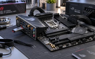
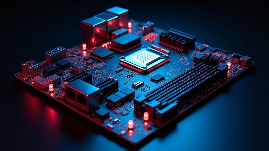
Every modern ASUS ROG, ProArt, and TUF motherboard — and their functional equivalents from MSI (EZ Debug LEDs), Gigabyte (Status LEDs), and ASRock (Dr. Debug) — ships with a row of four diagnostic LEDs positioned near the 24-pin ATX connector or the rear I/O panel. These indicators predate the physical display of a POST code readout and serve one unambiguous function: freeze the light at the last subsystem to fail initialization so the technician knows exactly where to focus.
POST (Power-On Self-Test) is the firmware-level hardware validation sequence executed by UEFI every time the system powers on. It probes each major subsystem in a fixed order — CPU u2192 DRAM u2192 GPU/VGA u2192 boot device — and halts with an error if any subsystem does not respond within specification. Q-LEDs illuminate in that same sequence and go dark when each stage passes. The one that stays lit is the one that failed.
Understanding this mechanism eliminates the guesswork that leads most builders to unnecessarily swap CPUs or GPUs before checking far simpler causes such as a misseated RAM stick, a missing CPU power connector, or a corrupted BIOS image.
The Four Q-LED Indicators: Full Diagnostic Reference Table
The table below maps each LED, its color convention across major vendors, the subsystem it monitors, the most statistically common root causes, and the field-proven first-response action.
| LED Label | Color (ASUS/MSI/Gigabyte) | Subsystem Monitored | Common Root Causes | First-Response Action |
|---|---|---|---|---|
| CPU | Red / Red / Red | Processor detection, VRM power delivery, socket integrity | Missing 8-pin CPU power, bent socket pins (LGA), unsupported CPU generation, failed VRM phase | Confirm all CPU power connectors seated; inspect LGA socket pins; cross-check CPU compatibility list (QVL) |
| DRAM | Yellow / Yellow / Yellow | Memory detection, training, and initialization | Incorrect slot population, XMP/EXPO profile instability, incompatible kit, dirty gold contacts | Remove all sticks, install one stick in A2 slot only, boot without XMP/EXPO; clean contacts with isopropyl alcohol |
| VGA | White / White / White | Discrete GPU and PCIe slot negotiation | GPU not fully seated, missing PCIe power connectors, failed GPU, PCIe slot damage, driver-level corruption on reboot loops | Reseat GPU; confirm all PCIe power plugs click; test in secondary x16 slot; try iGPU if available |
| BOOT | White / White / White | Storage device detection and bootloader handoff | NVMe drive not detected, corrupt bootloader, wrong boot order, M.2 slot sharing bandwidth with SATA ports | Enter UEFI; confirm drive appears in storage list; check M.2 slot compatibility note in manual; re-flash bootloader |
Vendor naming differs slightly: MSI labels these EZ Debug LEDs with identical color logic. Gigabyte uses a single two-character POST code display on higher-end boards (Z790 AORUS Master, X670E AORUS Extreme) in addition to LEDs. ASRock uses a two-digit alphanumeric Dr. Debug display that maps to AMI BIOS error codes.
Reading the POST Sequence Step by Step
A healthy POST traverses all four stages in under three seconds on a modern platform. Each LED flashes briefly as it tests, then extinguishes. The sequence to observe:
- All four LEDs illuminate simultaneously at power-on — this is normal, it is the initial LED test.
- CPU LED extinguishes first when the processor responds and VRM handshake completes.
- DRAM LED extinguishes after memory training. On first boot with a new XMP kit this can take 30–90 seconds — do not interrupt power during this phase.
- VGA LED extinguishes once the PCIe device is enumerated and the GOP (Graphics Output Protocol) driver loads.
- BOOT LED extinguishes when the UEFI hands off to the bootloader on the storage device.
- If any LED remains lit solid after 60 seconds, POST has halted at that subsystem.
CPU LED Solid: Diagnostic Protocol
A solid CPU LED is the most alarming result and the most misdiagnosed. Before concluding the processor is dead, execute this sequence in order:
- Verify the 8-pin (or dual 8-pin on HEDT) CPU power connector is fully seated — partial insertion is the single most common cause on new builds.
- Confirm the CPU is on the board’s official CPU Support List. An Intel Core Ultra 200-series CPU installed on a Z790 board without a BIOS update will produce a solid CPU LED because the firmware does not recognize the silicon.
- On Intel LGA platforms, visually inspect the socket under a flashlight for bent or missing pins. LGA1851 and LGA1700 have 1,700–1,851 pins respectively; even one bent pin can prevent initialization. Use a mechanical pencil barrel (no lead) to gently straighten a bent pin before escalating to RMA.
- On AMD AM5, pins are on the CPU package (LGA-style on socket side for AM5). Inspect the socket contacts for debris or corrosion.
- Perform a CMOS reset: remove the coin cell battery for 30 seconds with the PSU unplugged, reinstall, retry.
- Test with a known-good CPU if available. Only at this stage should CPU RMA be considered.
Thermal shutdown masquerading as a CPU LED is rare at POST but possible on a system that previously overheated and where the UEFI stores a thermal event flag. Review CPU temperature limits to understand the thermal thresholds that trigger protective shutdown. Also verify the cooler mount applies adequate pressure — a poorly mounted cooler can cause thermal runaway within seconds on modern high-TDP processors. Correct thermal paste application is a prerequisite before any overclocking diagnostic.
DRAM LED Solid: Diagnostic Protocol
Memory training failures are the most frequent cause of a halted POST on consumer builds, particularly with DDR5 kits running XMP/EXPO profiles above 6000 MT/s.
- Remove all sticks. Install a single stick in the A2 slot (the slot furthest from the CPU on most boards — confirm with manual). Boot without XMP enabled.
- If successful, add the second stick to B2, boot again, confirm stability.
- Only then enable XMP or EXPO. If the board fails to POST with XMP active, the profile is requesting voltages or timings the IMC (Integrated Memory Controller) cannot sustain. Drop the XMP frequency one tier or manually set primary timings looser by 2 CL.
- Clean DIMM gold contacts with a lint-free cloth dampened with 99% isopropyl alcohol. Oxidation on contacts is a genuine field issue, particularly in humid environments.
- Consult the motherboard’s DRAM QVL (Qualified Vendor List). Not every kit is validated; a kit absent from the QVL may require manual sub-timing adjustment. For background on what those speed ratings mean, see RAM speed and timings.
VGA LED Solid: Diagnostic Protocol
A solid VGA LED after GPU installation is almost always mechanical before it is electrical.
- Power off, discharge the PSU (hold power button 5 seconds after switching off at the PSU), then firmly reseat the GPU until the PCIe latch audibly clicks.
- Verify all required PCIe power connectors are attached. A flagship GPU such as the RTX 5090 or RX 9070 XT requires its full power budget at POST — do not assume it will boot without a connector to display an error.
- If the board has a secondary x16 slot, move the GPU there to eliminate a damaged primary slot.
- If the system has an iGPU (Intel Core with integrated graphics, or AMD APU), remove the discrete card, connect the monitor to the rear I/O display output, and boot to UEFI. This isolates the GPU as the failure point.
- On systems where a GPU driver update preceded the VGA LED halt, a corrupt GOP handoff can produce a false VGA LED. Boot to safe mode via the iGPU output and perform a GPU driver clean install using DDU before reinstalling the discrete card.
- For boards running the GPU in the primary PCIe 5.0 x16 slot, confirm the card is rated for PCIe 5.0 or is fully backward-compatible. Review PCIe 5.0 compatibility to understand slot negotiation behavior between generations.
BOOT LED Solid: Diagnostic Protocol
A BOOT LED halt means CPU, DRAM, and VGA all initialized successfully — the problem is storage or the bootloader, not silicon.
- Enter UEFI (Delete or F2 at power-on) and navigate to the storage information page. If the NVMe drive does not appear, the M.2 slot may be disabled due to bandwidth sharing — many Z790 and X670E boards disable specific M.2 slots when certain SATA ports are in use. Consult the board layout diagram.
- Confirm the M.2 drive is physically seated and the retention screw is tightened. An M.2 drive not held by its screw makes intermittent contact and produces exactly this symptom.
- If the drive appears in UEFI but Windows will not boot, the bootloader is corrupt. Boot from a Windows 11 installation USB, open Recovery, and run
bootrec /fixmbrfollowed bybootrec /rebuildbcd. - Check UEFI boot mode: a drive formatted with GPT requires UEFI boot mode; one formatted with MBR requires CSM/Legacy. Mismatches produce a BOOT LED halt even with a healthy drive.
Two-Digit POST Code Displays: Decoding AMI and Phoenix Codes
Higher-end boards from all four major vendors replace or supplement Q-LEDs with a two-character hexadecimal or alphanumeric display. These codes map to the Intel UEFI Platform Initialization specification and AMI Aptio BIOS event tables.
| POST Code | Phase | Meaning | Action |
|---|---|---|---|
00 |
Pre-BIOS | No POST activity; firmware not executing | Check PSU output, 24-pin, CPU power; suspect BIOS chip failure |
0d |
CPU Init | Microcode not found for installed CPU | Flash BIOS to latest version before installing new-gen CPU |
15 / 14 |
Pre-Memory | Memory detection failure | Single-stick in A2 slot, disable XMP |
55 |
Memory Init | No memory installed or detected | Reseat DIMM; clean contacts |
62 |
Memory Training | DDR training in progress (normal; wait) | Wait up to 3 minutes; do not power cycle |
99 |
PCIe Init | Super I/O / PCIe device initialization | Reseat GPU; remove all PCIe add-in cards except GPU |
A2 |
IDE/SATA/NVMe | IDE detect — storage enumeration failure | Verify drive in UEFI storage list; check M.2 screw and slot compatibility |
BIOS Flashback: Recovering a Board Without a CPU or RAM
ASUS BIOS FlashBack, MSI Flash BIOS Button, and Gigabyte Q-Flash Plus allow BIOS updates using only a powered PSU and a properly named file on a FAT32 USB drive — no CPU or RAM required. This is the correct path when a new CPU produces a solid CPU LED because the board’s firmware predates the processor’s microcode.
- Download the correct BIOS file from the vendor’s product page. Rename it exactly as the vendor specifies (e.g.,
ROG-MAXIMUS-Z890-APEX.CAPormsi.rom— the exact filename is mandatory). - Copy to the root of a FAT32-formatted USB drive. Plug into the designated BIOS FlashBack port (labeled on the rear I/O panel).
- With the system fully powered off but PSU switch on, press and hold the FlashBack button for 3 seconds. The indicator LED blinks during flash; solid light indicates completion.
- Do not interrupt power during the flash operation under any circumstances. A failed mid-flash is the one scenario that can permanently brick the BIOS chip on boards without a dual-BIOS backup.
Systematic Isolation: The Bare-Minimum POST Bench Test
When all LED-directed steps fail to resolve the issue, strip the system to absolute minimum hardware outside the chassis to eliminate shorting, incompatible components, and PSU power problems simultaneously.
- Place the motherboard on a non-conductive surface (the anti-static bag it shipped in, cardboard).
- Install CPU and CPU cooler only. Connect 24-pin ATX and 8-pin CPU power.
- Install one known-good RAM stick in the A2 slot.
- Connect a monitor to the rear I/O display output (iGPU) or install only the GPU.
- Short the power switch header pins with a flathead screwdriver to power on.
- If this bench configuration POSTs to UEFI, reintroduce components one at a time — GPU, storage, additional RAM — until the failure recurs. The last component added when the failure returns is the culprit.
This methodology eliminates chassis short circuits, failed front-panel buttons wired to power/reset headers, and PSU rail starvation caused by too many devices drawing power simultaneously — all real-world failure modes that produce misleading Q-LED readings.
Final Checklist Before RMA
- CMOS cleared via jumper or battery removal — not just the UEFI “Load Defaults” option
- CPU power connector (8-pin or dual 8-pin) fully seated — not a 4-pin in an 8-pin socket
- RAM tested in A2 slot only, single stick, no XMP/EXPO
- GPU reseated, all PCIe power connectors confirmed, tested in secondary slot
- BIOS updated to latest version via FlashBack if CPU is a newer generation
- Bench test outside chassis completed with minimum component set
- PSU tested with a PSU tester or known-good spare — a failing PSU produces every LED pattern imaginable and is frequently overlooked
Q-LEDs and POST code displays are precision diagnostic instruments embedded in every modern motherboard. Reading them correctly compresses a potential hours-long troubleshooting session into a targeted five-minute procedure. The LED does not guess — it reports exactly where the firmware stopped. Follow it precisely, isolate methodically, and reserve component swaps and RMA as a last resort after exhausting every software, seating, and power-delivery variable.