PCIe (PCI Express) slots are the backbone of modern motherboard expansion architecture, enabling high-speed communication between your CPU, GPU, storage drives, and peripheral devices. Understanding PCIe lanes, generation standards, and slot configurations is essential for anyone building a high-performance system, troubleshooting compatibility issues, or optimizing data transfer rates. This guide dissects PCIe slot technology with precision, covering everything from physical lane counts to real-world performance implications.
Quick Answer
PCIe slots are expansion ports on motherboards that connect graphics cards, storage controllers, and networking devices directly to your CPU via dedicated lanes. Slot designations (x16, x8, x4, x1) indicate the number of lanes—not physical size. PCIe 5.0 delivers up to 32 GB/s per x16 slot, with modern motherboards dynamically allocating lanes based on installed hardware and BIOS configuration.
What Is a PCIe Slot: Foundational Architecture
Defining PCIe and Slot Fundamentals
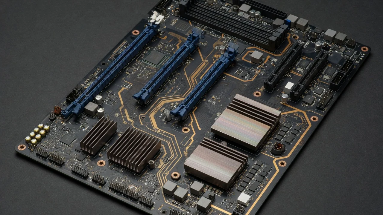
A PCIe (PCI Express) slot is a high-speed serial communication interface on your motherboard that connects expansion cards directly to the CPU or chipset. Unlike legacy parallel PCI slots, PCIe uses a serial point-to-point architecture with dedicated differential signal pairs called lanes. Each lane operates independently, allowing multiple cards to transfer data simultaneously without contention. The physical slot appearance may vary, but electrical lane count—denoted as x1, x4, x8, or x16—determines actual bandwidth capacity. A standard desktop motherboard typically features one primary x16 slot for graphics cards, supplemented by secondary x4 or x1 slots for storage and peripherals. To evaluate matched hardware tolerances, consult our detailed overview of mix nvme and sata ssd.
PCIe Lane Allocation and Physical Architecture
Modern x86 processors and chipsets have a fixed pool of PCIe lanes assigned by the CPU manufacturer. Intel 13th-gen and newer processors provide up to 20 lanes from the CPU die, while AMD Ryzen 7000 series delivers 24 lanes. These lanes can be configured as a single x16 connection, dual x8 links, or mixed configurations supporting x16+x4 or x8+x8+x4 topologies. The PCI-SIG PCIe Specification Standard defines electrical signaling, voltage levels (3.3V or 12V), and thermal operating ranges. Chipset lanes (typically 24–48 additional lanes) handle secondary M.2 slots, USB controllers, and SATA connections, isolated from CPU-direct lanes to prevent throttling of primary expansion cards.
PCIe Lane Designations Explained: x16, x8, x4, x1
Understanding Lane Count vs. Physical Size
The “x” notation in PCIe slot designations refers exclusively to electrical lane count, not physical dimensions. An x16 slot physically accommodates a x1 card (with mechanical keying), but a x1 card will only utilize one lane, delivering proportionally reduced bandwidth. Conversely, a high-bandwidth device like a graphics card test & GPU guide designed for x16 operation will underbenefit if installed in an x8 or x4 slot, experiencing 25–50% throughput degradation. Modern motherboards employ lane bifurcation—firmware-level splitting of CPU lanes—to dynamically allocate resources. For example, a motherboard with 20 CPU lanes can operate as x16 for a single GPU or reconfigure to x8+x8 for dual-GPU setups in PCIe 4.0 or 5.0 systems.
Bandwidth Specifications by Generation and Lane Count
| PCIe Standard | Per-Lane Speed | x1 Bandwidth | x4 Bandwidth | x8 Bandwidth | x16 Bandwidth |
|---|---|---|---|---|---|
| PCIe 3.0 | 1.97 GB/s | 1.97 GB/s | 7.88 GB/s | 15.75 GB/s | 31.51 GB/s |
| PCIe 4.0 | 3.94 GB/s | 3.94 GB/s | 15.75 GB/s | 31.51 GB/s | 63.01 GB/s |
| PCIe 5.0 | 7.88 GB/s | 7.88 GB/s | 31.51 GB/s | 63.01 GB/s | 126.02 GB/s |
| PCIe 6.0 (Emerging) | 15.75 GB/s | 15.75 GB/s | 63.01 GB/s | 126.02 GB/s | 252.04 GB/s |
PCIe 5.0 represents a doubling of per-lane speed over 4.0, translating to x16 bandwidth of 126.02 GB/s—sufficient for advanced AI inference, high-speed NVMe RAID, and dual-GPU machine learning workloads. Most consumer boards released since 2022 support PCIe 5.0 on primary x16 slots, while secondary slots often operate at PCIe 4.0 or 3.0 due to chipset limitations. When evaluating motherboards like the ASUS ROG Maximus Z890 Hero vs MSI MEG Z890 ACE, confirm the PCIe generation of each expansion slot, not just the primary one.
PCIe 5.0 and Modern Standards: What Is PCIe 5?
PCIe 5.0 Specifications and Practical Performance
PCIe 5.0 doubles the signaling rate to 32 GT/s (gigatransfers per second) per lane, achieving 126.02 GB/s full duplex bandwidth on x16 slots. This standard enables real-time applications like 8K video capture, AI model training on consumer hardware, and enterprise-class NVMe storage arrays. However, PCIe 5.0’s higher frequencies (up to 32 GHz) demand improved signal integrity, shielding, and thermal management. Many PCIe 5.0 devices implement Active Cooling—integrated fans or heatsinks—to maintain junction temperatures below 85°C during sustained operations. The what is pcie 5 question often arises in forums because consumer adoption lags enterprise rollout; as of 2024, most gaming GPUs and consumer NVMe drives operate at PCIe 4.0, with PCIe 5.0 reserved for flagship models and server-grade expansion cards. To evaluate matched hardware tolerances, consult our detailed overview of mix nvme and sata ssd.
Backward and Forward Compatibility Considerations
PCIe maintains full backward compatibility across generations. A PCIe 4.0 GPU will function in a PCIe 5.0 x16 slot at PCIe 4.0 speeds; conversely, PCIe 3.0 cards operate safely in newer slots with automatic negotiation to the lowest common denominator. This architectural design ensures hardware longevity—cards purchased today remain usable in future motherboards. However, performance scaling is nonlinear. A RTX 4090 or Radeon RX 9060 XT 8GB vs 16GB comparison graphics card running on PCIe 3.0 x16 (31.51 GB/s) versus PCIe 5.0 x16 (126.02 GB/s) rarely shows measurable frame rate differences in 2024 gaming workloads, as GPU memory bandwidth and core counts remain the bottleneck. Professional applications—ray tracing, CUDA compute, AI inference—demonstrate 5–12% improvements in PCIe 5.0 environments with high-bandwidth peripherals.
Slot Types, Configurations, and Real-World Allocation Patterns
Primary Slot (CPU-Direct x16) Behavior and GPU Assignment
The topmost PCIe x16 slot on virtually all consumer motherboards connects directly to the CPU, ensuring lowest latency and highest bandwidth availability. This slot is always prioritized for discrete GPUs, M.2 NVMe drives with integrated PCIe controllers, or high-speed storage adapters. When a GPU is installed, the CPU firmware automatically allocates x16 lanes (or x8 if bifurcation is active and a second slot is occupied). If no GPU is present, the BIOS may reassign lanes to the second PCIe slot or to M.2 sockets. This dynamic allocation is transparent to users but critical for troubleshooting: if you install a second GPU without enabling bifurcation in BIOS, both cards will negotiate x8 operation, reducing aggregate throughput by 50%.
Secondary and Tertiary Slots: Chipset Routing and Lane Sharing
Secondary x16 (electrical x8 or x4) and x4 slots typically route through the chipset, introducing 200–500 ns additional latency compared to CPU-direct lanes. Chipset PCIe lanes are shared among multiple devices: secondary slot lanes, M.2 sockets, SATA controllers, and USB hubs all draw from the same pool. Installing a high-bandwidth NVMe drive in a secondary M.2 slot can reduce available bandwidth for a secondary GPU. Most motherboards clearly document this lane sharing in the manual under “PCIe Lane Configuration” or “Slot Priority Hierarchy.” For example, a Z890 motherboard might allocate lanes as: 20 lanes from CPU (x16 GPU or x8+x8 dual GPU), 24 lanes from chipset shared across four M.2 sockets and two secondary expansion slots. When planning workspace deployment, consider the engineering criteria outlined in our pcie riser cable signal degradation guide.
PCIe Error Detection, Recovery, and Diagnostic Metrics
Understanding PCIe PEX Error Recovery Counters
The term what is pcie pex errors recovery counter refers to firmware-level diagnostics tracking link-level communication failures. When a PCIe device experiences signal integrity issues—loose cables, electromagnetic interference, or driver software conflicts—the host controller increments error counters and may attempt link retraining. Most BIOS implementations expose these counters in advanced diagnostics menus under labels like “PCIe Lane Error Count” or “PEX Recovery Events.” A healthy system should show zero recovery events over weeks of operation; sustained counts above 10 per hour indicate hardware failure (bad slot, defective card, or cable damage) requiring immediate investigation. Professional diagnostic tools like GPU-Z or CPU-Z’s advanced PCIe tab display real-time error rates; persistent non-zero values warrant slot swapping or device replacement.
Signal Integrity, Thermal Management, and Degradation Patterns
PCIe signals operate at increasingly high frequencies: PCIe 5.0 demands 32 GHz per-lane signaling with strict jitter tolerances (u00b12 ns). Environmental factors degrade signal integrity: ambient temperatures above 35°C, dust accumulation on connectors, and capacitive coupling from adjacent power rails all contribute to error rates. Devices running at 85°C or higher experience exponential increases in bit error rates. Quality expansion cards implement onboard temperature sensors and throttling; a GPU that reduces clock speeds under thermal stress automatically reduces data transmission rate, preventing catastrophic link failure. When diagnosing intermittent PCIe errors, systematically check: slot cleanliness, card seating pressure, BIOS firmware version (updates often include PCIe stability patches), and ambient temperature (ideally 20–28°C for overclocked systems). For additional operational safety benchmarks, see our published testing notes on thunderbolt 4 vs usb4 difference.
Practical Applications: GPU, Storage, and Networking Use Cases
Graphics Card Bandwidth Requirements and Scaling
Modern GPUs like those reviewed in our graphics card tests & GPU guides rarely saturate PCIe 3.0 x16 bandwidth in typical gaming scenarios. The RTX 4090, RTX 5090, and RX 9080 XT all operate at peak performance over PCIe 3.0 x16 (31.51 GB/s) for gaming and content creation. However, professional applications—real-time ray tracing at 8K resolution, AI model training, and scientific simulation—can achieve 5–15% performance gains with PCIe 5.0 due to reduced latency in host-to-device memory transfers. When pairing high-end CPUs (like the AMD Ryzen 5 9600X vs Intel Core Ultra 5 245K) with flagship GPUs, PCIe 5.0 support future-proofs the system for emerging workloads and streaming protocols requiring high-bandwidth peripheral communication.
NVMe Storage and Dual-Drive Configurations
High-speed NVMe drives formatted for PCIe 4.0 or 5.0 require dedicated x4 lanes for full performance. A PCIe 4.0 x4 NVMe achieves ~7.4 GB/s sequential read speeds; PCIe 5.0 x4 doubles this to ~14.8 GB/s. If a motherboard has only one primary M.2 slot connected to CPU lanes, installing a second NVMe in a chipset-routed secondary slot automatically reduces primary slot bandwidth or introduces lane sharing contention. Boards with dual CPU-direct M.2 slots (rare in consumer SKUs, common in high-end ROG and MEG models) allow simultaneous full-speed operation of two drives. Verify motherboard specifications before purchasing multiple high-speed NVMe drives; many budget and mid-range boards throttle secondary drives to x2 or x1 operation.
Networking and RAID Controllers
10 GbE or faster network adapters require PCIe x4 minimum (15.75 GB/s in PCIe 4.0); 40 GbE cards demand x8 or x16. RAID controllers with battery-backed cache benefit from PCIe x8 lanes to avoid bottlenecking disk array throughput. When installing a high-performance network card and high-speed storage expansion simultaneously, confirm the motherboard supports simultaneous full-bandwidth operation via BIOS documentation and lane allocation tables. Many enthusiast boards prioritize GPU lanes first, reducing networked-card performance if GPU allocation is x8+x8 bifurcation. To compare alternative configurations, check our hands-on review of how to clear cmos.
Troubleshooting PCIe Issues: Diagnosis and Resolution Frameworks
Common PCIe Failure Modes and Symptoms
No POST / System Hangs on Startup: Card not fully seated, incompatible firmware, or power delivery failure. Solution: Remove card, reseat with firm pressure (audible click), verify 6-pin/8-pin PCIe power connectors, update BIOS.
Card Recognized in BIOS but Not OS: Driver missing, PCIe link training failure, or BIOS configuration. Solution: Check Device Manager for unknown devices, install chipset drivers from motherboard manufacturer, disable/enable slot in BIOS, try alternative slot. Users looking for related component recommendations can explore our atx vs matx vs itx breakdown.
Intermittent Disconnects or Throttling: Thermal throttling, electromagnetic interference, or defective card. Solution: Improve airflow to 20–28°C ambient, reseat expansion card and power connectors, test card in different slot or another system.
Reduced Performance vs. Specifications: Operating at lower lane count (x8 instead of x16) due to BIOS misconfiguration or disabled bifurcation. Solution: Enter BIOS, search “Bifurcation,” “Lane Configuration,” or “Slot Mode” menus, enable x16 or desired configuration, save and reboot.
Diagnostic Tools and Command-Line Utilities
Windows: Use Device Manager PCIe link speed reporting, PCIe Link Speed column in GPU-Z, or msinfo32 for DirectX device tree. Linux: Execute lspci -vvv | grep -i "link" to display negotiated PCIe version and lane count per device. Cross-platform: AIDA64 Engineer Edition, HWInfo64, or vendor-specific tools (NVIDIA NVIDIA-SMI for CUDA devices, AMD ROCm tools) provide real-time PCIe statistics and error counters. When submitting bug reports or RMA requests, include lspci output and BIOS version to accelerate diagnostics.
Final Diagnostic Verdict & Maintenance Checklist
System Health Verification Protocol
- Monthly: Inspect slot connectors for dust; use compressed air to clean PCIe slot edges and card contact surfaces. Verify no visual debris around capacitors or power delivery stages near slots.
- Quarterly: Run full system diagnostics—AIDA64 Stress Test, GPU-Z sustained load test, and memtest86—to validate PCIe link stability under peak load. Monitor PCIe error counters; any increase above baseline warrants investigation.
- Annually: Update motherboard BIOS (if stability patches are released), verify expansion card firmware versions, and stress-test all M.2 and secondary expansion slots to confirm lane allocation.
- Before Major Upgrades: Document current PCIe configuration (BIOS screenshots, lspci output, Device Manager hierarchy). When replacing the GPU or installing new storage, confirm lane bifurcation settings and thermal headroom for new hardware.
Modern Motherboard Selection Criteria
Evaluate motherboards based on PCIe slot count and generation, not slot count alone. A Z890 or X870E board should feature at least PCIe 5.0 on the primary x16 GPU slot and secondary x8 or x4 slots at PCIe 4.0. Verify CPU vs. chipset lane allocation by cross-referencing the motherboard manual against CPU specifications from the manufacturer’s site. Prioritize boards with clearly documented lane sharing—if installing a GPU and dual NVMe drives, ensure both drives connect to CPU-direct lanes or the GPU won’t suffer bandwidth reduction. For content creation and high-bandwidth workloads, choose boards offering x8+x8 bifurcation support and multiple CPU-routed M.2 sockets.
PCIe slot technology continues evolving rapidly. PCIe 6.0 prototype controllers have been demonstrated in lab environments, promising 252.04 GB/s x16 bandwidth, but consumer product availability remains 3–5 years away. Today’s PCIe 5.0 systems provide ample future-proofing for gaming, content creation, and professional computing through 2027–2029. By understanding lane allocation, error diagnostics, and thermal constraints, you ensure maximum lifespan and optimal performance from your expansion hardware.
Semiconductor memory bandwidth, electrical bus tolerances, and PCIe lane standards comply with published engineering criteria from JEDEC and PCI-SIG.
Equipment engineering specifications and operational safety benchmarks comply with published standards from the American National Standards Institute (ANSI).