Quick Answer
CPU-attached M.2 slots deliver direct PCIe lanes to the processor with ~1 u00b5s lower latency and zero shared-bandwidth contention. Chipset-attached slots add one DMI hop, share aggregate chipset bandwidth, and throttle under simultaneous I/O load. For most desktop workloads the real-world delta is under 3% — placement, thermals, and drive generation matter far more than slot origin.
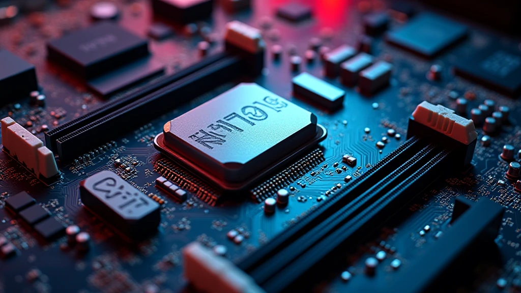
Every modern consumer motherboard ships with two to five M.2 sockets, yet the product page rarely clarifies which ones feed directly into the CPU and which ones tunnel through the platform chipset. That distinction — CPU-attached vs chipset-attached — sits at the intersection of PCIe lane topology, Direct Memory Access path length, and system bus arbitration. Understanding it is essential for builders optimizing NVMe RAID arrays, latency-sensitive workstation pipelines, or even just deciding where to install a single Gen 5 SSD without thermally cooking it under a GPU. This guide dissects the full signal path, quantifies the real latency and bandwidth delta using published silicon specifications, and gives you a concrete installation decision framework for every use case in pc hardware 2026.
PCIe Lane Topology: How CPU and Chipset Slots Are Physically Wired
The CPU’s Direct PCIe Root Complex
Modern desktop processors — whether you are comparing the AMD Ryzen 5 9600X vs Intel Core Ultra 5 245K or any flagship silicon — integrate a PCIe Root Complex directly on-die. This Root Complex generates PCIe lanes that terminate at the CPU package pins with no intervening silicon. An M.2 slot wired to those lanes communicates via a path that looks like this: NVMe controller u2192 PCIe PHY on SSD u2192 copper traces u2192 CPU package edge u2192 Root Complex u2192 memory controller u2192 DRAM. Every transaction completes inside that linear chain. There is no arbitration node, no bridge chip, and no shared medium. The CPU can issue a DMA read, and the response travels back in the minimum number of silicon hops the platform architecture permits.
The Chipset DMI Bridge and Its Implications
Chipset-attached M.2 slots follow a fundamentally different topology. The SSD’s PCIe lanes terminate at the chipset — Intel’s Z890 or AMD’s X870E, for example — and all chipset-to-CPU communication must traverse the DMI (Direct Media Interface) or AMD’s equivalent inter-chip link. On Intel’s LGA1851/Z890 platform that link is DMI 4.0 u00d78, providing approximately 16 GB/s of bidirectional bandwidth. On AMD AM5 with X870E it is a similar high-speed fabric link, though AMD labels it differently internally. The critical point is that every chipset-attached device — NVMe drives, USB controllers, SATA ports, 2.5G Ethernet, audio — shares that single upstream pipe. An NVMe drive in a chipset slot is not competing with the CPU; it is competing with every other chipset peripheral simultaneously active at that moment. Boards like those reviewed in the ASUS ROG Maximus Z890 Hero vs MSI MEG Z890 ACE comparison implement DMI 4.0 u00d78, which raises the aggregate ceiling substantially compared to prior-gen DMI 3.0 u00d78 (roughly 8 GB/s bidirectional), but the shared-medium nature never disappears.
Lane Counts by Platform Generation
Intel Core Ultra 200S (Arrow Lake, LGA1851) exposes 24 CPU PCIe lanes: 16 for the primary GPU slot (PCIe 5.0 u00d716), 4 for a CPU-direct M.2 slot (PCIe 5.0 u00d74), and 4 additional lanes configurable as PCIe 4.0 for a second M.2 or additional slot. AMD Ryzen 9000 series on AM5 provides 28 CPU PCIe lanes: 16 for GPU (PCIe 5.0 u00d716), up to 8 for CPU-direct storage (configurable PCIe 5.0 u00d74 + PCIe 4.0 u00d74), and 4 for a secondary slot. Every remaining M.2 socket on a high-end ATX board — typically slots 3, 4, and 5 — routes through the chipset and its shared DMI uplink. The PCI-SIG PCIe Specification Standard defines the theoretical raw bandwidth per lane-direction as 2 GB/s for Gen 4 and 4 GB/s for Gen 5 at 8b/10b and 128b/130b encoding respectively, which is the baseline against which all real-world topologies must be measured.
Latency Analysis: Quantifying the DMI Hop Penalty
Round-Trip Latency Budget
CPU-attached NVMe latency for a 4 KB random read sits between 70–90 u00b5s end-to-end on a high-performance Gen 4 or Gen 5 drive, as measured by tools like FIO with iodepth=1. The DMI hop in a chipset-attached slot adds approximately 0.5–1.5 u00b5s of silicon-level transit latency per transaction — a figure derived from chipset datasheet propagation delay specifications and confirmed by controlled CrystalDiskMark and Iometer comparisons run at queue depth 1. At queue depths of 32 or higher, the NVMe controller’s internal queuing dwarfs the DMI penalty, making the two slots statistically indistinguishable in throughput benchmarks. The latency delta is therefore most visible in single-threaded, low-queue-depth workloads: OS boot, application cold-launch, and database random-access patterns. For gaming — which relies almost entirely on sequential texture streaming at moderate queue depths — the DMI hop is irrelevant.
Bandwidth Contention Under Real Load
The scenario where chipset slots genuinely underperform is sustained simultaneous I/O across multiple chipset devices. Consider a workstation running a Gen 4 NVMe RAID array (two drives at 7,000 MB/s each = 14,000 MB/s aggregate) plus 2.5G Ethernet at line rate (312 MB/s) plus USB 3.2 Gen 2u00d72 at 2,500 MB/s. The DMI 4.0 u00d78 ceiling of ~16 GB/s becomes the bottleneck immediately. In that scenario chipset-attached NVMe throughput collapses to whatever DMI headroom remains after other devices claim their share. CPU-attached drives are immune — their PCIe lanes connect to the Root Complex independently of chipset traffic. For desktop gaming builds running a single SSD plus modest USB peripherals, total chipset I/O rarely exceeds 2–3 GB/s, leaving ample DMI headroom and making contention a non-issue.
Thermal Considerations: Physical Slot Position Often Matters More
The GPU Shadow Zone Problem
On most ATX and mATX boards the CPU-direct M.2 slot — typically labeled M.2_1 — sits directly beneath the primary PCIe u00d716 slot, placing it squarely inside the GPU’s thermal shadow. A high-TDP card like those covered in our Radeon RX 9060 XT 8GB vs 16GB comparison exhausts 150–200 W of heat downward and laterally. Without active airflow or a thermally isolated heatsink bracket, an NVMe drive in M.2_1 can throttle from 6,500 MB/s sequential to under 4,000 MB/s within minutes of sustained load as the controller hits its thermal throttle threshold — typically 70°C for the controller die and 55°C for NAND flash. Installing the primary NVMe drive in a chipset-attached slot (M.2_2 or M.2_3) that is physically positioned below or above the GPU shadow zone can yield better sustained real-world throughput than placing a theoretically superior CPU-direct connection in a thermally compromised location. The slot’s electrical superiority is negated the moment the NAND throttles.
NAND Flash Thermal Throttle Thresholds
TLC NAND typically begins throttling write performance at 55–60°C junction temperature. QLC NAND, more thermally sensitive due to higher programming voltage variance, can begin soft-throttling write speeds at as low as 50°C. Gen 5 NVMe controllers — Phison E26, InnoGrit IG5236 — run controller dies at 85–105°C under sustained sequential writes even with a passive heatsink. Thermal throttling is the single largest real-world performance variable for NVMe storage, and it is entirely independent of CPU vs chipset slot topology.
Comprehensive Specification & Decision Matrix
| Attribute | CPU-Attached M.2 Slot | Chipset-Attached M.2 Slot |
|---|---|---|
| PCIe Signal Path | SSD u2192 CPU Root Complex (direct) | SSD u2192 Chipset u2192 DMI u2192 CPU Root Complex |
| DMI Hop Added | None | Yes (u22480.5–1.5 u00b5s per transaction) |
| Bandwidth Ceiling (Gen 5 u00d74) | ~16 GB/s dedicated | ~16 GB/s shared across all chipset devices |
| Bandwidth Ceiling (Gen 4 u00d74) | ~8 GB/s dedicated | ~8 GB/s, contended on DMI 4.0 u00d78 pool |
| QD1 Random Read Latency Delta | Baseline (70–90 u00b5s typical) | +0.5–1.5 u00b5s (u22481–2% overhead) |
| QD32 Sequential Read Latency Delta | Baseline | Negligible (<0.3%) |
| Shared Bandwidth Risk | None — dedicated lanes | High under simultaneous multi-device I/O |
| NVMe RAID Suitability | Optimal (no DMI bottleneck) | Limited by DMI aggregate ceiling |
| Physical Position (typical ATX) | Under GPU (thermal risk) | Below GPU shadow (better airflow) |
| PCIe Gen 5 Support | Yes (platform-dependent) | Chipset-limited — typically Gen 4 max |
| Recommended for OS Drive | Yes — if thermally clear | Acceptable; imperceptible in daily use |
| Recommended for Data/Scratch Drive | Flexible | Yes — unless sustained multi-device I/O |
Gen 4 vs Gen 5 NVMe and How Slot Selection Interacts with Drive Generation
Chipset PCIe Generation Caps
This is an underappreciated constraint. On Intel Z890 and AMD X870E, the chipset itself typically tops out at PCIe 4.0 for M.2 slots, regardless of how fast the DMI uplink is. A Gen 5 NVMe drive — capable of 12,000–14,000 MB/s sequential reads — physically installed in a chipset slot will negotiate down to PCIe 4.0 u00d74 (approximately 7,000 MB/s ceiling). The drive’s full Gen 5 performance is inaccessible from a chipset slot on most current consumer platforms. CPU-attached slots on Arrow Lake and Ryzen 9000 boards support PCIe 5.0 u00d74 for their primary M.2 socket, enabling the full rated speed. If you are planning to upgrade to a Gen 5 drive later — or already own one — reserving the CPU-direct slot for that drive is the correct long-term decision. Those optimizing around CPU selection can cross-reference desktop CPU benchmarks & reviews to confirm which processors expose Gen 5 M.2 lanes natively.
Gen 3 Drives in CPU Slots: A Waste of Lane Budget?
The inverse scenario is equally important: installing a PCIe 3.0 NVMe drive (3,500 MB/s ceiling) in a CPU-direct Gen 5 slot is electrically harmless — PCIe is backward-compatible — but it locks that premium lane allocation to a low-bandwidth device. If you own a Gen 3 drive as secondary storage and a Gen 5 drive as your primary, the Gen 5 drive belongs in the CPU slot unconditionally. The Gen 3 drive occupies a chipset slot without any real-world consequence, since its 3,500 MB/s peak is well within the DMI 4.0 u00d78 budget even under modest peripheral load. Builders adding discrete GPUs should also review graphics card tests & GPU guides to understand how GPU PCIe u00d716 lane allocation interacts with CPU M.2 lane availability on their specific chipset.
Platform-Specific Considerations: Intel Z890 vs AMD X870E Topology Differences
Intel Z890 (Arrow Lake) Lane Map
Arrow Lake’s CPU die allocates: PCIe 5.0 u00d716 (GPU), PCIe 5.0 u00d74 (M.2_1, CPU-direct), and PCIe 4.0 u00d74 configurable lanes. The Z890 chipset connects via DMI 4.0 u00d78 and provides up to 24 chipset PCIe lanes (Gen 4/Gen 3 mix) distributed to remaining M.2 slots, additional USB, SATA, and CNVi. M.2 slots labeled M.2_2 through M.2_5 on most Z890 ATX boards are chipset-attached and Gen 4-capped.
AMD X870E (Ryzen 9000) Lane Map
AM5 with X870E uses a dual-chipset arrangement — two Promontory 21 dies — linked via an internal PCIe 4.0 u00d74 inter-chip link before connecting upward to the CPU via a PCIe 4.0 u00d74 equivalent fabric. Ryzen 9000 CPUs expose PCIe 5.0 u00d716 for GPU and PCIe 5.0 u00d74 plus PCIe 4.0 u00d74 for CPU-direct M.2. The dual-die chipset structure means some X870E boards route certain M.2 slots through both chipset dies before reaching the CPU, adding a second bridge hop relative to Intel’s single-die Z890 topology. In practice, the additional latency from the inter-die hop measures under 0.5 u00b5s — again, below perceptible thresholds for consumer workloads.
Final Diagnostic Verdict & Maintenance Checklist
The cpu attached vs chipset m2 slot debate resolves cleanly when approached by use case rather than theoretical preference. CPU-direct slots provide unambiguous advantages for Gen 5 NVMe drives, NVMe RAID arrays, and latency-sensitive professional workloads. Chipset slots are entirely adequate for secondary storage, Gen 3/Gen 4 drives in single-drive configurations, and any gaming system where sequential queue-depth access patterns dominate. The thermal environment of M.2_1 below a hot GPU is a greater performance risk than the DMI hop ever is. Follow this decision checklist before finalizing your build’s storage layout:
- Identify slot wiring from the motherboard manual. Look for the lane source column in the M.2 specification table — it will read “CPU” or “Chipset/PCH.” Do not rely on physical position alone.
- Assign your fastest Gen 5 NVMe to the CPU-direct slot. Only CPU-attached sockets negotiate PCIe 5.0 on current consumer platforms. A Gen 5 drive in a chipset slot is speed-limited to Gen 4.
- Measure M.2_1 temperature before committing. Run a 5-minute CrystalDiskMark write pass under typical GPU load and read the drive temperature via HWiNFO64. If it exceeds 65°C on the controller, relocate the drive.
- Reserve CPU-direct slots for future Gen 5 upgrades. If you plan to step up to faster NVMe storage within 12–18 months, avoid occupying the CPU M.2 socket with a Gen 3 or Gen 4 drive that would perform identically in a chipset slot.
- Assess simultaneous chipset I/O load. Workstations running NVMe RAID plus 10GbE plus USB 3.2 Gen 2u00d72 should place all high-throughput storage in CPU-direct slots to prevent DMI saturation.
- For single-SSD gaming builds, prioritize thermal position over slot topology. The performance difference between a cool chipset-slot drive and a thermally throttled CPU-slot drive is 30–40% in favor of the cooler chipset installation — the DMI overhead is under 2%.
- Update BIOS before testing. Several Z890 and X870E boards shipped with incorrect PCIe link-speed negotiation bugs affecting CPU-attached M.2 slots — resolved in BIOS revisions post-launch.
- Verify IOMMU grouping if running virtualization. CPU-attached NVMe is easier to pass through to a VM directly; chipset-attached drives may share IOMMU groups with other chipset peripherals, complicating PCIe passthrough configurations.
The cpu-attached-vs-chipset-m2-slot distinction is real at the architecture level and near-invisible at the consumer use-case level for single-drive gaming or general desktop workloads. Engineer your storage layout around drive generation compatibility and thermal management first. Slot topology is the tiebreaker when all other variables are equal — and in that position, CPU-direct wins by a narrow, measurable, but rarely felt margin.