Quick Answer
A CPU fan running at full speed almost always signals thermal stress, a misconfigured or missing fan curve, dried thermal interface material, or a blocked heatsink. Correct the root cause first, then tune the fan curve in BIOS or dedicated software. Noise drops within minutes without sacrificing thermals.
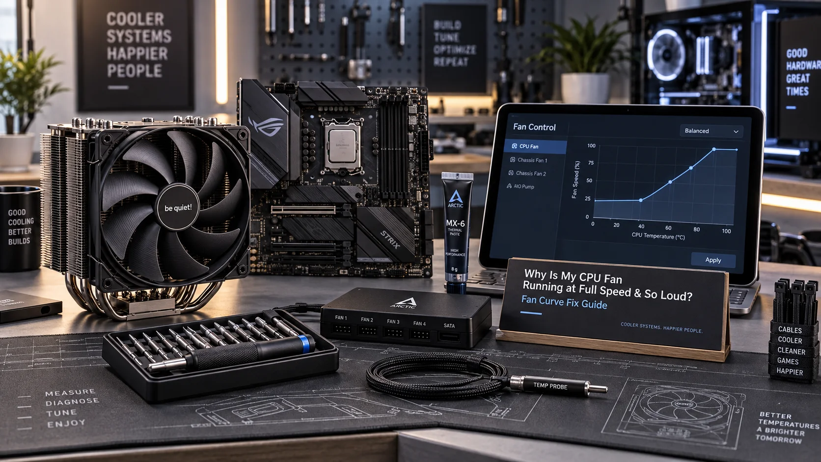
A CPU fan that suddenly screams at 3,000+ RPM — or never throttles down from POST — is not a minor nuisance. It is a hardware alarm. The fan control subsystem on every modern motherboard is engineered to modulate fan speed against CPU die temperature using a programmable curve stored in firmware. When that curve is absent, corrupted, or overridden, or when the thermal load itself is legitimately excessive, the fan defaults to maximum RPM as a failsafe. Understanding which condition is driving the noise determines the correct fix. This cpu fan loud fix guide walks through every layer: thermal physics, firmware configuration, mechanical inspection, and software profiling — covering Intel Arrow Lake and AMD Ryzen 9000-series platforms as they ship in pc hardware 2026 configurations.
Why the CPU Fan Defaults to Full Speed: Root Cause Architecture
Modern motherboards implement fan control through a dedicated Super I/O chip or embedded controller — commonly ITE, Nuvoton, or Fintek silicon — that reads thermistor data from the CPU socket and drives PWM signals to connected fan headers. The PWM duty cycle maps directly to a fan curve stored in CMOS. When the controller cannot read a valid temperature (open-circuit thermistor, corrupt CMOS, absent CPU), it defaults to 100% duty cycle. The fan is not broken; it is operating exactly as designed under uncertainty.
PWM vs DC Fan Control: Why It Matters
4-pin PWM fans modulate speed by varying the width of a 25 kHz control pulse on pin 4, keeping motor voltage constant. 3-pin DC fans modulate speed by varying voltage on pin 2. A 4-pin fan plugged into a 3-pin header loses PWM control entirely and runs at whatever voltage the header supplies — often full voltage, producing full speed. Verify header type and fan type match before assuming a firmware problem exists.
The Failsafe 100% Duty Cycle Trigger
UEFI firmware from AMI, Phoenix, and InsydeH2O all share a common design rule: if the CPU temperature sensor reports above a hard thermal limit, if the sensor value is invalid (0°C or 255°C raw), or if the BIOS setting CPU Fan Speed Low Limit is set higher than the actual fan’s idle RPM, the system throws a POST warning and locks fan speed to maximum. This is the single most common reason a CPU fan runs loud immediately after a build or BIOS reset.
Diagnostic Symptom Matrix: Identify Your Exact Failure Mode
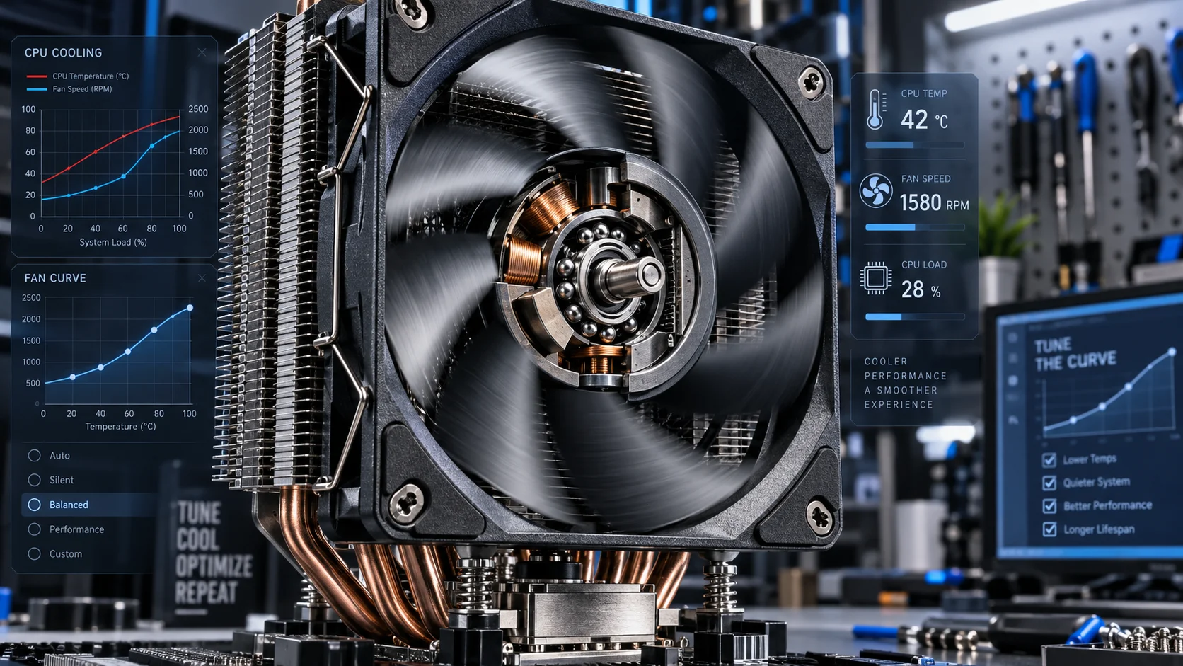
Before touching any setting, cross-reference observed behavior against the table below. Each failure mode has a distinct signature and a targeted fix path. Misdiagnosing thermal paste degradation as a fan curve error — or vice versa — wastes time and risks hardware damage.
| Symptom | Likely Root Cause | CPU Temp at Idle | CPU Temp Under Load | Primary Fix |
|---|---|---|---|---|
| Fan loud from POST, never slows | Missing or reset fan curve in BIOS | 35–45°C (normal) | 65–80°C (normal) | Reconfigure fan curve in UEFI |
| Fan loud only under gaming/render load | Aggressive stock curve, high TDP | 35–50°C (normal) | 85–100°C (elevated) | Repaste + custom fan curve |
| Fan loud + system unstable or throttling | Degraded TIM, blocked heatsink | 55–70°C (high) | 95–105°C (critical) | Clean + repaste immediately |
| Fan loud + rattling or grinding noise | Bearing wear or cable contact | Normal range | Normal range | Replace fan unit |
| Fan loud after BIOS update | CMOS reset wiped fan profile | Normal range | Normal range | Re-enter custom fan curve |
| Fan loud + POST warning “CPU Fan Error” | Fan RPM below BIOS low-limit threshold | Normal range | Normal range | Lower RPM low-limit in BIOS |
Fix 1 — Reconfigure the Fan Curve in UEFI Firmware
This is the highest-leverage fix for the cpu fan loud fix scenario where temperatures are normal but fan speed is not. Enter UEFI by pressing Delete, F2, or F10 at POST — the key varies by board. Navigate to Hardware Monitor, Q-Fan Control (ASUS), Smart Fan (MSI), or Fan Tuner (Gigabyte). Every modern Z890 and X870E board exposes a graphical fan curve editor. For platform-specific BIOS layout differences, the ASUS ROG Maximus Z890 Hero vs MSI MEG Z890 ACE comparison covers firmware UI differences in depth.
Optimal Fan Curve Target Points
A well-engineered fan curve for a 125W TDP air-cooled system should follow this profile: hold 30–35% PWM duty cycle (roughly 700–900 RPM on a quality 120mm fan) between 30–60°C; ramp linearly to 60% duty cycle at 75°C; reach 80% at 85°C; and allow 100% only above 90°C. This keeps acoustics under 35 dBA during light workloads while still protecting the die at sustained all-core loads. Processors like those covered in the AMD Ryzen 5 9600X vs Intel Core Ultra 5 245K comparison have meaningfully different thermal behaviors — Ryzen 9000 series runs cooler at idle due to TSMC 4nm density, while Intel Core Ultra 200S tiles generate more localized hotspot heat requiring a more aggressive ramp above 80°C.
The CPU Fan Speed Low Limit Setting
Locate the CPU Fan Speed Low Limit option — typically set to 600 RPM by default. If a low-noise aftermarket cooler or AIO pump idles below this threshold, the board triggers the fan error warning and forces maximum speed. Set this value to 200 RPM or Ignore for AIO installations where the pump header is separate from the CPU_FAN header.
Fix 2 — Thermal Interface Material Inspection and Replacement
Thermal paste is a consumable. Standard silicone-based compounds (Arctic MX-4, Noctua NT-H1) begin to dry and crack after 3–5 years of thermal cycling. Metal-matrix and phase-change compounds degrade faster under repeated high-delta-T cycles. Dried TIM increases junction-to-heatsink thermal resistance by 3–8°C/W depending on gap thickness, directly raising CPU die temperature by 10–20°C under sustained load — which in turn forces the fan curve into its upper operating range continuously.
TIM Replacement Procedure
- Power down, discharge static, remove the cooler mounting bracket.
- Clean old TIM from both the IHS and heatsink base with 90%+ isopropyl alcohol and lint-free wipes. Never use acetone on copper or nickel-plated bases.
- Apply a pea-sized dot (approximately 0.3 mL) of new compound centered on the IHS. Spreading manually increases air entrapment risk — let cooler pressure distribute it.
- Reinstall with even torque on diagonal screws using a cross-pattern sequence to prevent IHS warping under mounting pressure.
- Allow 30 minutes of mixed load for the paste to fully seat before thermal benchmarking.
Heatsink Fin Stack and Fan Blade Cleaning
Dust compaction in heatsink fin arrays is mechanically equivalent to reducing fin surface area. A fin stack at 40% dust occlusion forces the remaining open area to dissipate the same wattage, increasing airflow velocity requirements and therefore fan RPM. Use 30-second bursts of compressed air (held vertical to prevent propellant discharge) from the exhaust side of the heatsink, not the intake side, to avoid forcing debris deeper into the fins. Repeat annually in average desktop environments, every 6 months in carpeted or pet-occupied rooms.
Fix 3 — Software Fan Control with Hardware-Level Precision
When BIOS fan curve tools are limited — common on budget B-series boards — software controllers running at the OS level can provide finer granularity. Fan Control (by Ru00e9mi Mercier, open-source) and HWiNFO64 + Fan Control plugin are the current best-in-class tools for Windows 10/11. They read sensor data via WMI and ACPI and write PWM commands directly to EC registers, bypassing Windows’ own thermal policy layer which is too conservative by default.
Configuring a Mixed-Sensor Curve
Advanced software controllers allow fan speed to respond to a mix of sensors — CPU die temperature AND CPU socket temperature AND VRM temperature simultaneously. This is superior to BIOS-only control because it prevents VRM thermal runaway scenarios where the CPU is cool but the power delivery circuitry is overheating, a failure mode particularly relevant to high-core-count workstation builds. For GPU-adjacent thermal interactions, see the graphics card tests & GPU guides covering airflow coupling between CPU and GPU thermal zones.
Per Intel Architecture Technical Documentation, the PROCHOT# (processor hot) signal asserts at Tjmax — 100°C for most Core Ultra 200S SKUs — triggering automatic frequency reduction independent of fan speed. Software fan control that prevents temperatures from approaching Tjmax eliminates throttling events and maintains full boost clock availability, a measurable performance benefit beyond acoustics alone.
Fix 4 — Case Airflow, Cable Management, and Ambient Conditions
A correctly configured fan curve is ineffective if the case airflow path is restricted. The CPU cooler exhausts heat into the case interior; that heat must exit the chassis before recirculating back to the intake. Positive pressure configurations (more intake CFM than exhaust CFM) reduce dust ingestion but can increase CPU inlet temperature by 3–5°C compared to balanced or slightly negative pressure setups. For high-TDP CPUs, balanced pressure with direct rear and top exhaust aligned to the cooler’s airstream direction is the optimal configuration.
Cable Management Impact on Thermal Resistance
Unmanaged cable bundles routed across the front intake panel reduce effective fan face area by up to 30% and create turbulent dead zones inside the chassis. Route all modular PSU cables behind the motherboard tray. Use cable combs on GPU power cables to reduce cross-sectional obstruction in the GPU-to-CPU airstream path. This is not aesthetic preference — it is documented airflow physics. For context on high-TDP GPU heat contributions to the same chassis thermal budget, the Radeon RX 9060 XT 8GB vs 16GB comparison includes thermal dissipation data relevant to mid-tower chassis planning.
Ambient Temperature and Seasonal Variation
CPU fan speed is always relative to ambient. A system configured for 21°C ambient will run noticeably louder at 30°C ambient because the same fan curve produces higher temperatures at every point, shifting the operating region up the RPM ramp. If summer noise is significantly worse than winter, the fan curve configuration is not accounting for ambient delta. Use the Mixed Sensor mode in software, or increase the BIOS fan curve’s temperature offsets by +5°C during summer months. For broader CPU platform context, the desktop CPU benchmarks & reviews section includes thermal profiling data across multiple ambient conditions.
Final Diagnostic Verdict & Maintenance Checklist
A loud CPU fan is a symptom stack, not a single failure. The fix path follows a strict priority sequence: eliminate thermal emergencies first, then correct firmware configuration, then optimize for acoustics. Skipping to fan curve tuning while a legitimate thermal problem exists masks a real hardware risk. Execute the following checklist in order before declaring the system resolved.
- Measure first: Open HWiNFO64 or HWMonitor and record CPU Package temperature at idle and under a 10-minute Cinebench R24 nT load before changing anything.
- Check header type: Confirm the CPU fan is connected to a 4-pin PWM CPU_FAN header, not a SYS_FAN header or a 3-pin DC-only header.
- Inspect BIOS fan curve: Enter UEFI, navigate to fan control, verify a valid curve exists. If BIOS was recently updated, the curve was likely reset to default aggressive profile.
- Check RPM low-limit: Set CPU Fan Speed Low Limit to 200 RPM or Ignore in BIOS to eliminate false fan-error failsafe triggers.
- Inspect TIM condition: If the system is over 3 years old or CPU idle temps exceed 50°C in a 21°C room, plan an immediate repaste.
- Clean heatsink and fans: Compressed air flush of fin stack and fan blades, verifying no cable contact with fan blades causing intermittent rattling at high RPM.
- Audit chassis airflow: Confirm positive or balanced pressure configuration, cable bundles cleared from intake paths, and cooler exhaust direction aligned with case exhaust fans.
- Deploy software control if BIOS tools are insufficient: Fan Control (open-source) with a mixed CPU + VRM sensor curve, targeting sub-40 dBA at idle and sub-50 dBA at full load.
- Re-benchmark after each change: A change that drops CPU temp by 8°C at load drops fan noise by 3–5 dBA — measurable, audible, and confirmable. Do not stack multiple changes before measuring.
- Schedule maintenance: Annual dust removal, 3-year TIM replacement cycle, BIOS fan curve re-verification after every firmware update.
The overwhelming majority of cpu fan loud fix cases resolve at step 3 (BIOS curve reset) or step 5 (TIM degradation). Mechanical fan failure — bearing wear requiring physical replacement — accounts for under 10% of reported cases and is identifiable by its characteristic grinding or intermittent clicking signature that persists regardless of RPM command. A fan that is simply loud at high RPM is doing its job; the engineering task is ensuring it never needs to.